


7.9.4. TAM INTERFACE CIRCUIT
This circuit is to switch between FAX receiving and the external TAM’s message recording
automatically. This circuit consists of an EXT. TAM OFF-HOOK detect circuit, monitor
transformer, multiplexer, amplifier, and VOX detect circuit.
For details, please refer to
TAM INTERFACE SECTION
().
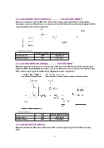
7.9.5. PULSE DIAL CIRCUIT AND ON / OFF HOOK CIRCUIT
While OFF-HOOK, RLY101 is ON. Q102 turns on by pin (138) of IC501 as well. On the other hand,
while ON-HOOK, Q102 turns OFF by pin (138) of IC501, then the line turns OFF. ON/OFF-HOOK,
controlled by pin (138) of IC501, makes the pulse dial operation possible.
IC501 (138) LINE RLY Low Level CN517 (12) CN101 (12) Q102 OFF RLY101 OFF : DC
Loop OFF
IC501 (138) LINE RLY High Level CN517 (12) CN101 (12) Q102 ON RLY101 ON : DC
Loop ON
7.9.6. LINE AMPLIFIER AND SIDE TONE CIRCUIT
1. Circuit Operation
The reception signal output from the line transformer T101 is
input to pin (2) of IC101 via C112 and R112 and then the signal is
amplified at pin (1) of IC101 and sent to the reception system at
11.6dB.
The transmission signal goes through C571 and R579 and enters
IC511-pin (2), where the signal is amplified to about 24.8dB. Then,
it is output from pin (1) of IC101 and transmitted to T101 via C125
and R121. If the side tone circuit is not applied, the transmission
signal will return to the reception amplifier via C112 and R112.
When the side tone circuit is active, the signal output from IC101
pin (1) passes through C125, R123, C122, C115 and R115 and
goes into the amplifier IC101 pin (3). This circuit is used to cancel
the transmission return signal.
186
Summary of Contents for KX-FHD332C
Page 33: ...3 Open the back cover 4 Remove the jammed recording paper 33 ...
Page 46: ...5 1 DISASSEMBLY FLOW CHART 5 1 1 UPPER CABINET SECTION 46 ...
Page 49: ...5 2 2 HOW TO REMOVE THE OPERATION PANEL BLOCK 49 ...
Page 50: ...5 2 3 HOW TO REMOVE THE OPERATION BOARD AND LCD 50 ...
Page 51: ...5 2 4 HOW TO REMOVE THE IMAGE SENSOR CIS 51 ...
Page 52: ...5 2 5 HOW TO REMOVE THE THERMAL HEAD 52 ...
Page 53: ...5 2 6 HOW TO REMOVE THE PLATEN ROLLER AND BACK COVER 53 ...
Page 54: ...5 2 7 HOW TO REMOVE THE PICKUP ROLLER 54 ...
Page 55: ...5 2 8 HOW TO REMOVE THE CASSETTE LEVER 55 ...
Page 56: ...5 2 9 HOW TO REMOVE THE BOTTOM FRAME 56 ...
Page 57: ...5 2 10 HOW TO REMOVE THE DIGITAL ANALOG POWER SUPPLY SENSOR BOARDS AND AC INLET 57 ...
Page 58: ...5 2 11 HOW TO REMOVE THE MOTOR BLOCK AND SEPARATION ROLLER 58 ...
Page 59: ...5 2 12 HOW TO REMOVE THE GEARS OF MOTOR BLOCK 59 ...
Page 60: ...5 3 INSTALLATION POSITION OF THE LEAD WIRES 60 ...
Page 74: ...2 Left margin Top margin 3 Thermal head 1 dot 74 ...
Page 77: ...CROSS REFERENCE PROGRAM MODE TABLE 6 4 2 PROGRAM MODE TABLE 77 ...
Page 81: ...Note The above values are the default values 6 5 3 HISTORY 81 ...
Page 90: ...Fig B 90 ...
Page 98: ...6 6 4 12 A BLANK PAGE IS RECEIVED 98 ...
Page 116: ...116 ...
Page 117: ...CROSS REFERENCE TEST FUNCTIONS 117 ...
Page 118: ...CROSS REFERENCE TEST FUNCTIONS 118 ...
Page 119: ...CROSS REFERENCE TEST FUNCTIONS 119 ...
Page 120: ...CROSS REFERENCE TEST FUNCTIONS 120 ...
Page 121: ...121 ...
Page 122: ...122 ...
Page 123: ...123 ...
Page 128: ...128 ...
Page 133: ...I O and Pin No Diagram 6 6 7 1 CHECK THE STATUS OF THE DIGITAL BOARD 133 ...
Page 139: ...3 No ring tone or No bell CROSS REFERENCE CHECK SHEET 139 ...
Page 142: ...6 6 9 2 TROUBLESHOOTING FLOW CHART 142 ...
Page 143: ...143 ...
Page 144: ...144 ...
Page 148: ...CROSS REFERENCE TEST FUNCTIONS 6 6 13 THERMAL HEAD SECTION Refer to THERMAL HEAD 148 ...
Page 149: ...7 CIRCUIT OPERATIONS 7 1 CONNECTION DIAGRAM 149 ...
Page 152: ...7 3 CONTROL SECTION 7 3 1 BLOCK DIAGRAM 7 3 2 MEMORY MAP 152 ...
Page 153: ...7 3 3 ASIC IC501 This custom IC is used for the general FAX operations 153 ...
Page 155: ...155 ...
Page 188: ...7 10 ITS Integrated Telephone System AND MONITOR SECTION 7 10 1 GENERAL 188 ...
Page 200: ...8 3 1 ITU T No 1 TEST CHART 8 3 2 ITU T No 2 TEST CHART 200 ...
Page 201: ...9 FIXTURES AND TOOLS 201 ...
Page 202: ...10 CABINET MECHANICAL AND ELECTRICAL PARTS LOCATION 10 1 GENERAL SECTION 202 ...
Page 203: ...10 2 OPERATION PANEL SECTION 203 ...
Page 204: ...10 3 BACK COVER SECTION 204 ...
Page 205: ...205 ...
Page 206: ...10 4 UPPER CABINET SECTION 206 ...
Page 207: ...10 5 LOWER CABINET P C BOARD SECTION 207 ...
Page 208: ...CROSS REFERENCE MOTOR SECTION 10 6 MOTOR SECTION 208 ...
Page 209: ...10 7 ACTUAL SIZE OF SCREWS 11 ACCESSORIES AND PACKING MATERIALS 209 ...
Page 210: ...12 REPLACEMENT PARTS LIST Notes 1 RTL Retention Time Limited Note 210 ...
Page 231: ...SW502 SW501 CN501 CHECK PFUP1301ZA 1 3 KX FHD332C SENSOR BOARD PCB5 ...