26
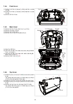
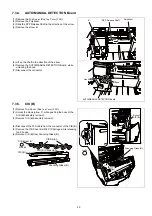
7.2.4.
Front Cover
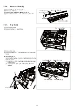
7.2.5.
Back Cover
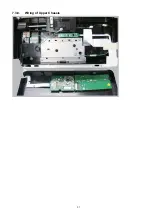
7.2.6.
Top Cover
(1) Pull the Front Cover (2 arrows
1
) at the same time to unlock
3 hooks.
(2) Pull the Front Cover (2 arrows
2
) at the same time to unlock
3 hooks.
(3) Remove the Front Cover.
(1) Remove the Front Cover. (See
))
(2) Remove the screw C and H.
(3) Remove the AC Inlet cover.
(4) Remove the AC Inlet from the Back Cover.
(5) Open the ADF Door.
(6) Unlock the 2 hooks of the back side, while pulling the Back
Cover (2 arrows
1
).
(7) Unlock the 4 hooks of the upper side, while expanding the
Back Cover (2 arrows
2
).
(8) Remove Back Cover (arrow
3
).
(1) Pull the Top Cover (2 arrows
1
) at the same time to unlock 2
hooks
PANEL SWITCH Board and LCD PANEL Board (KV-S10xxC)
) for the detail position of the hooks.
(2) Pull the Top Cover (1 arrows
2
) to unlock the center hook.
(3) Pull the Top Cover (2 arrows
3
) at the same time to unlock 2
hooks.
(4) Remove the Top Cover and disconnect the FFC cable.
PANEL SWITCH Board and LCD PANEL Board (KV-S10xxC)
) for the cable position.
Front Cover
2
1
1
Hook
2
AC Inlet Cover
AC Inlet
Exit Tray
C
Back Cover
H
Back Cover
ADF Door
Hook
1
1
2
3
2
Top Cover
1
3
3
1
2
Summary of Contents for KV-S1057C
Page 7: ...7...
Page 9: ...9 3 Location of Controls and Components 3 1 Main Unit...
Page 10: ...10...
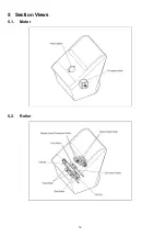
Page 16: ...16 5 Section Views 5 1 Motor 5 2 Roller...
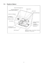
Page 17: ...17 5 3 Board and Sensor...
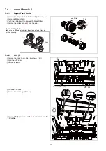
Page 31: ...31 7 3 8 Wiring of Upper Chassis...
Page 128: ...128 14 Exploded View and Replacement Parts List...
Page 133: ...133 14 3 Feed Tray Assembly 302 305 302 303 307 301 306 305 302 304 Feed Tray Assembly...
Page 188: ...Index 74 8 Operating Manual Table of Contents...
Page 255: ...PNQX6995ZA DD0914HS0 Panasonic System Networks Co Ltd 2014...

