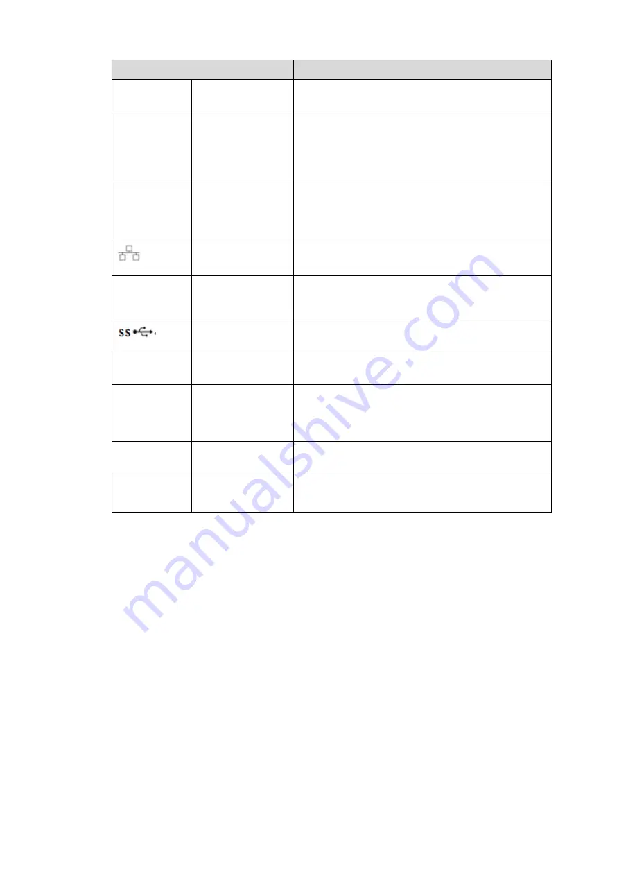
Panasonic K-NL316G Quick Start Manual Download Page 9


Name  

Function  

port 

RS485_B.It is the cable B. You can connect to the 

control devices such as speed dome PTZ. 

CTRL 12V 

Controller 12V power output. It is to control the on-

off alarm relay output. It can be used to control the 

device alarm output. At the same time, it can also 

be used as the power input source of some 

devices such as the alarm detector. 

+12V 

+12V power output port. It can provide the power 

to some peripheral devices such as the camera or 

the alarm device. Please note the supplying power 

shall be below 1A. 


Network port 

10M/100M/1000Mbps self-adaptive Ethernet port. 

Connect to the network cable. 

eSATA 

eSATA port 

External SATA port. It can connect to the device of 

the SATA port. Please jump the HDD when there 

is peripheral connected HDD. 


USB3.0 port 

USB3.0 port. Connect to mouse, USB storage 

device, USB burner and etc. 

RS-232 

RS232 debug 

COM. 

It is for general COM debug to configure IP 

address or transfer transparent COM data. 

HDMI 

High Definition 

Media Interface 

High definition audio and video signal output port. 

It transmits uncompressed high definition video 

and multiple-channel data to the HDMI port of the 

display device. HDMI version is 1.3 

VGA 

VGA video output 

port 

VGA video output port. Output analog video signal. 

It can connect to the monitor to view analog video. 

PoE  PORTS 

16 PoE ports 

Built-in Switch. Support PoE. The 16 PoE ports 

series products supports total 150W power. One 

PoE port max supports 15W. 


Summary of Contents for K-NL316G

Page 1: ...Network Disk Recorder Quick Start Guide Model No K NL316K G Version 1 0 0 ...

Page 2: ...el 1 1 3 After Remove the Chassis 1 1 4 HDD Installation 1 1 5 Front Panel 2 1 6 Rear Panel 4 2 Connection Sample 6 3 GUI Operation 7 3 1 Login 7 3 2 Remote Device 8 3 3 Schedule 10 3 4 Realtime Playback 13 4 Web Operation 14 4 1 Network Connection 14 4 2 Login 15 4 3 Main Window 16 4 3 1 LAN Login 16 4 3 2 WAN Login 16 ...

Page 3: ...ii Welcome Thank you for purchasing our network disk recorder This quick start guide is designed to be a reference tool for your system ...

Page 4: ... for any problems caused by unauthorized modifications or attempted repair 5 Environment The NVR should be installed in a cool dry place away from direct sunlight inflammable explosive substances and etc This series product shall be transported storage and used in the specified environments 6 Accessories Be sure to use all the accessories recommended by manufacturer Before installation please open...

Page 5: ... according to your purchase order The label in the rear panel is very important too Usually we need you to represent the serial number when we provide the service after sales 1 3 After Remove the Chassis Please check the data cable power cable COM cable and main boar cable connection is secure or not 1 4 HDD Installation Important Please turn off the power before you replace the HDD The pictures l...

Page 6: ... Change setup increase decrease numeral Assistant function such as PTZ menu Switch channel when playback Left 2 Right 3 Switch current activated controls move up and down When device is in 1 channel playback mode use it to control playback control bar process Play Pause 6 When playback click it to pause click it again to play again Reverse Pause 5 When playback click it to begin reverse play Fast ...

Page 7: ...play assistant function PTZ control and image color In menu control interface click to switch PTZ control menu In motion detection setup working with Fn and direction keys to realize setup Backspace function in numeral control or text control press it for 1 5seconds to delete the previous character before the cursor In HDD information interface click to switch HDD record time and other information...

Page 8: ...t port 1 16 There are four groups The first group is from port 1 to port 4 the second group is from port 5 to port 8 the third group is from 9 to 12 and the fourth group is from 13 to 16 They are to receive the signal from the external alarm source There are two types NO normal open NC normal close When your alarm input device is using external power please make sure the device and the NVR have th...

Page 9: ...TA eSATA port External SATA port It can connect to the device of the SATA port Please jump the HDD when there is peripheral connected HDD USB3 0 port USB3 0 port Connect to mouse USB storage device USB burner and etc RS 232 RS232 debug COM It is for general COM debug to configure IP address or transfer transparent COM data HDMI High Definition Media Interface High definition audio and video signal...

Page 10: ...6 2 Connection Sample The front panel is shown as in Figure 2 1 The figure for reference only Figure 2 1 ...

Page 11: ...n you can see system goes to login interface Tips Check the box Startup button here system goes to startup wizard again when it boots up the next time Cancel the Startup button system goes to the login interface directly when it boots up the next time Figure 3 1 Click Cancel button or Next Step you can see the login interface Please input user name and password See Figure 3 2 System consists of fo...

Page 12: ...2 Remote Device From Main menu SETTING REMOTE REMOTE device or right click mouse on the preview interface and then select remote device item you can see the following interface See Figure 3 3 Figure 3 3 Tips In the preview interface for the channel of no IPC connection you can click the icon in the center of the interface to quickly go to the Remote Device interface See Figure 3 4 and Figure 3 5 F...

Page 13: ...the interface System supports batch add function Click Manual Add button you can add a device directly See Figure 3 6 Important Please note the manual add function is for Panasonic the others and custom When the type is the custom you can just input URL address username and password connect to the network camera without considering network camera manufacture Please contact your network camera manu...

Page 14: ...oliday It is to set holiday setup Please note you need to go to the General interface Main Menu SETTING SYSTEM GENERAL Holiday to add holiday first Otherwise you can not see this item Pre record System can pre record the video before the event occurs into the file The value ranges from 1 to 30 seconds depending on the bit stream Redundancy System supports redundancy backup function It allows you b...

Page 15: ... all the setups please click save button system goes back to the previous menu See Figure 3 11 There are color bars for your reference Green color stands for regular recording yellow color stands for motion detection and red color stands for alarm recording The white means the MD and alarm record is valid Once you have set to record when the MD and alarm occurs system will not record neither motio...

Page 16: ...12 Figure 3 10 Figure 3 11 ...

Page 17: ...nds and has no operation the control bar automatically hides Figure 3 12 SN Name SN Name SN Name 1 Realtime playback 2 Digital zoom 3 Manual record 4 Manual Snapshot 5 Remote device Realtime playback button is to playback the previous 5 60 minutes record of current channel Please go to the Main Menu SETTING SYSTEM GENERAL to set real time playback time System may pop up a dialogue box if there is ...

Page 18: ...rt PoE device may try to set a corresponding IP address of the Switch network adapter First system tries to set via arp ping It then uses DHCP if it finds the DHCP is enabled After successfully set IP address system may use Switch to send out broadcast system thinks the connection is OK when there is any response Now system is trying to login the newly found IPC Now please check the interface you ...

Page 19: ...available 4 When you insert PoE all channels are in use now System can pop up a dialogue box for you to select a channel to overwrite The title of the pop up interface is the name of the current operation PoE port In this interface All PoE channel become grey and cannot select 4 2 Login Open IE and input NVR address in the address column For example if your NVR IP is 192 168 0 250 then please inpu...

Page 20: ...See Figure 4 2 Click the channel name on the left side you can view the real time video Figure 4 2 4 3 2 WAN Login In WAN mode after you logged in the interface is shown as below See Figure 4 3 Figure 4 3 For detailed operation information please refer to the User s Manual included in the resources CD ...

Page 21: ...emarks or trademarks of Microsoft Corporation in the United States and or other countries Microsoft product screen shot s reprinted with permission from Microsoft Corporation Intel and Intel Core are trademarks of Intel Corporation in the U S and other countries Adobe Acrobat Reader and Reader are either registered trademarks or trademarks of Adobe Systems Incorporated in the United States and or ...

Reviews: