

Confirm the following items are included in the camera’s packaging.
Installation Guide (this document) .......... 1 pc.
RJ45 waterproof connector ................. 1 bag.
Template (Dome type only) ..................... 1 pc.
CD-ROM ............................................... 1 pc.
Standard accessories
Connection
Device external cable
You can refer to the following figure for cable information.
1
2
12V DC
GND
1. LAN (Network port) ................ RJ45 waterproof jack. Connect to standard Ethernet cable.
NOTE:
Some devices do not support PoE power supply.
2. 12V DC (Power input port) ..... Power port. Input 12V DC.
When a PoE power supply is used to power the camera, the
power input port is not used. Process the jack as indicated below.
<Dome type>
Protect the jack with tape or the like to prevent dust and moisture
from collecting inside.
<Bullet type>
Appropriate waterproof treatment is performed.
Assembling RJ45 waterproof connector
IMPORTANT:
z
The maximum cable length is 100 m.
z
Make sure that the PoE device in use is compliant with IEEE802.3af standard.
z
Use all 4 pairs (8 pins) of the Ethernet cable.
z
The external dimensions of the Ethernet cable are ø5 mm to ø6.5 mm.
z
If the procedure for the RJ45 waterproof connector (accessory) part is not correctly followed,
the waterproofing may be compromised. Do not install the camera where the RJ45
waterproof connector is exposed to constant rain or moisture.
1
Attach the rubber ring (accessory) to the RJ45
waterproof jack connected to the camera as shown.
z
Attach with the flat surface of the rubber ring facing
the RJ45 waterproof jack.
2
First pass the Ethernet cable through the RJ45
waterproof connector cap (accessory), the inner rubber
(accessory) and then RJ45 waterproof connector cover
(accessory).
Next, use a specialized tool (locally procured) to crimp
the RJ45 plug (locally procured) to the end of the
Ethernet cable.
z
Pass the inner rubber over the cable so that the
grooved surface faces the RJ45 plug and the flat
surface faces the Ethernet cable.
3
Insert the inner rubber into the far end of the waterproof
connector cover (the direction in which multiple tabs
are open) to secure it temporarily inside the multiple
tabs.
The following steps illustrate how to attach the connector
to a camera as it is being installed.
4
Connect the RJ45 plug to the RJ45 waterproof jack
and then rotate and tighten firmly the RJ45 waterproof
connector cover.
5
Connect the RJ45 waterproof connector cap to the
RJ45 waterproof connector cover and rotate the RJ45
waterproof connector cap until there is no gap between
it and the RJ45 waterproof connector cover.
Connect 12 V DC AC adaptor to the power port (if necessary)
When the camera will run on an external power supply, use an AC adaptor that can provide a 12 V
DC 0.5 A or higher power supply.
IMPORTANT:
When cables are used outdoors, there is a chance that they may be affected by lightning.
In this case, install a lightning arrester just before where the cables connect to the camera.
CAUTION:
z
A READILY ACCESSIBLE DISCONNECT DEVICE SHALL BE INCORPORATED TO THE
EQUIPMENT POWERED BY 12 V DC POWER SUPPLY.
z
ONLY CONNECT 12 V DC CLASS 2 POWER SUPPLY (UL1310/CSA 223) or LIMITED
POWER SOURCE (IEC/EN/UL/CSA 60950-1).
RJ45
waterproof jack
Rubber ring
Flat surface
RJ45 plug
(locally
procured)
RJ45
waterproof
connector
cover
(accessory)
RJ45
waterproof
connector
cap
(accessory)
Ethernet
cable
(locally
procured)
Flat surface
Inner rubber
(accessory)
Multiple tabs
RJ45 waterproof
jack
Framework and dimension
Please refer to the following figure for dimension information.
Side view
Bottom view
17 mm
{21/32 inches}
85 mm (H)
{3-11/32 inches}
Decorative ring
Enclosure
Camera body
3-ø5 mm
{3/16 inches}
ø84 mm
{3-5/16 inches}
ø108 mm
{4-1/4 inches}
Pedestal
Device Installation
Secure the camera with 3 screws (M4) (locally procured).
IMPORTANT:
z
Before starting the connection, turn off the power of the devices to be connected.
z
Procure 3 screws (M4) to secure the camera to a ceiling or a wall, according to the material of
the installation area. In this case, wood screws and nails should not be used.
z
Required pull-out capacity of a single screw or anker is 196 N {20 kgf} or more.
Step 1 Remove the decorative ring and pedestal from the camera.
Turn the decorative ring counterclockwise relative to the camera body to remove it.
Next, release the three pedestal tabs against the enclosure, and remove the pedestal as well.
NOTE:
Be careful not to drop the camera, which will no longer be supported by the pedestal once it is removed.
Step 2 Open a hole for cabling in the ceiling or wall.
Remove the template from the carton box and use it to open holes in the positions for installation
screws and the center position to pass cabling through.
NOTE:
z
Determine the screw hole diameter based on screw specifications.
z
As the cabling hole diameter, open a hole in the center of the template.
Step 3 Installing the pedestal to the ceiling or wall.
Pull the cabling through the cabling hole in the ceiling or wall, and fix the pedestal to the ceiling or
wall with 3 screws (M4).
Step 4 Connect the camera.
Connect the RJ45 waterproof connector to the camera's RJ45
waterproof jack. (Refer to steps
4
and
5
in “Assembling RJ45
waterproof connector”.)
If necessary, also connect the plug of an AC adaptor for 12 V
DC power to the power port.
Step 5 Attach the camera body and enclosure to the
pedestal.
Temporarily tilt the camera so that the camera sensor section
faces the bottom of the monitoring screen, and attach the
camera body and enclosure using the three pedestal tabs.
NOTE:
After connection, push extra cabling through the hole in the
ceiling or wall to adjust the length.
Step 6 Turn the power on and check the screen on
the computer.
Turn on power from the 12 V DC power supply or PoE device
and operate the camera. Check video from the camera on the
computer screen and refer to “Network Configuration” on the
right side of this document.
Step 7 Adjust the camera angle.
Adjust the camera angle as you check video on the computer
screen. Turn the enclosure to pan, or move the camera itself to
adjust tilt or yaw.
Step 8 Attach the decorative ring.
Finally, insert the decorative ring from the camera body side, and
turn it clockwise to secure it.
NOTE:
When cabling is passed through the side of the camera, it can
only pass through the slit of the pedestal and decorative ring, as
shown to the right.
Before opening installation holes in the ceiling or walls,
determine the direction in which you will route cabling, and
arrange the template accordingly before installation work.
Three pedestal tabs
Sensor
PAN
TILT
YAW
Decorative ring
K-EF134L02AE/K-EF134L03AE/K-EF134L06AE
K-EW114L03AE/K-EW114L06AE
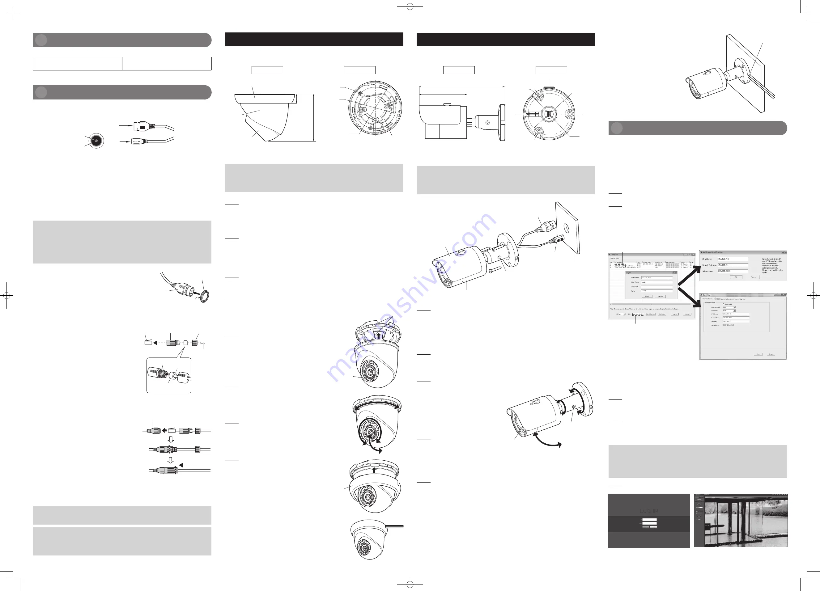
Framework and dimension
Please refer to the following figure for dimension information.
165 mm {6-1/2 inches}
92 mm {3-5/8 inches}
3-ø4.5 mm
{3/16 inches}
ø56 mm
{2-7/32 inches}
ø70 mm
{2-3/4 inches}
Side view
Rear view
Device Installation
Secure the camera with 3 screws (M4) (locally procured).
IMPORTANT:
z
Before starting the connection, turn off the power of the devices to be connected.
z
Procure 3 screws (M4) to secure the camera to a ceiling or a wall, according to the material of
the installation area. In this case, wood screws and nails should not be used.
z
Required pull-out capacity of a single screw is 196 N {20 kgf} or more.
Sunshade
Screw (M4) ×3
(locally procured)
Wall or Ceiling
Locking screw
RJ45 Waterproof jack
Power port
Camera body
* The figure shows the camera with
the sunshade extended.
Step 1 Open a hole for cabling in the ceiling or wall.
Refer to the dimensional diagram of the base portion of the camera above and mark the hole
positions on the ceiling or wall, then drill holes for the installation screws and the center position to
pass cabling through.
NOTE:
z
Determine the screw hole diameter based on screw specifications.
z
As the cabling hole diameter, open a hole in the center of the base portion of the camera.
Step 2 Connect the camera.
Connect the RJ45 waterproof connector to the camera’s RJ45 waterproof jack. (Refer to steps
4
and
5
in “Assembling RJ45 waterproof connector”.)
If necessary, also connect the plug of an AC adaptor for 12 V DC power to the power port.
Step 3 Installing the camera.
Loosen the locking screw and fix the camera to
the ceiling or wall with three screws (M4) while
panning and tilting of the camera as shown to
the right.
NOTE:
After connection, push extra cabling through the
hole in the ceiling or wall to adjust the length.
Step 4 Turn the power on and check
the screen on the computer.
Turn on power from the 12 V DC power supply
or PoE device and operate the camera. Check
video from the camera on the computer screen
and refer to “Network Configuration” on the right
side of this document.
Step 5 Adjust the camera angle.
Adjust the camera angle as you check video on
the computer screen. Turn the base of the
camera to pan, or move the camera itself to
adjust tilt or yaw, as shown at upper right.
Adjust TILT or PAN angle of the camera so that
the camera sensor section faces the bottom of
the monitoring screen.
Finally, tighten the locking screw to secure the
camera’s position.
(Recommended tightening torque:
0.78 N·m {8 kgf·cm})
PAN
TILT
YAW
Sensor
Locking screw
Network Configuration
The IP address of all the cameras is the same when shipping factory (default IP192.168.0.10), in
order to make the camera get access to the network smoothly,
please plan the useable IP segment reasonably according to the actual network environment.
Modify IP Address
IP address can be acquired and modified through the “Config Tool” for the cameras which are
accessed via wired network.
In this manual, it will introduce the approach of modifying IP address via the “Config Tool”; also you
can modify the IP address in the network parameters of the web interface.
Step 1
Double click the “ConfigTool.exe” in the CD-ROM and open the “Config Tool”.
Step 2
Double click the device to be configured, the system will pop out the “Login” dialog box. Log in using
the default user name and password. Enter the new IP address, Default Gateway and Subnet Mask
into the “IP Address Modification” dialog box, then click “OK”, or enter them into the Network
Parameter tab of “Config Tool”, then click “Save”.
NOTE:
The default user name and password are “admin” and “12345”.
Default camera IP address
Computer IP address
If the computer IP address and camera IP
address are in different segments
If the computer IP address and camera IP
address are in the same segment
or
Login WEB Interface
NOTE:
Different devices may have different web interfaces, the figures below are just for
reference, please refer to the document <<WEB Operation Manual>> in the CD-ROM and the
actual interface for more details.
Step 1
Open IE and input the camera IP address in the address bar.
Alternatively, in “Config Tool”, right-click the IP address in the “Device List” and click “Open Device
Web” to open the webpage.
Step 2
The login interface is shown below, please input default user name and password (Default user
name is “admin” and password is “12345” respectively), click “login”.
When you log in for the first time, a window prompting you to update the password will pop up.
Please enter your own new password.
IMPORTANT:
z
Use a combination of characters and numbers that is difficult to guess.
Avoid using a string of the same characters, such as “11111”, birth dates, or telephone
numbers.
z
Change passwords periodically.
z
Be sure to manage the configured user names and passwords carefully.
Step 3
Install controls according to the system prompt. The “Live” page will be displayed.
See support web page below for further details.
http://security.panasonic.com/pss/security/library/e-series.html
NOTE:
When cabling is passed through the side of the
camera, it can only pass through the slit of the
base portion of the camera, as shown to the
right.
Before opening installation holes in the ceiling or
walls, determine the direction in which you will
route cabling before installation work.
Slit of the base
portion of the camera