background image


Step 3  
If you want to modify the device IP address without logging in the device web interface, you can go to 
the configuration tool main interface to set.  
In the configuration tool search interface (Figure 3-), please select a device IP address and then 
double click it to open the login interface. Or you can select an IP address and then click the Login 
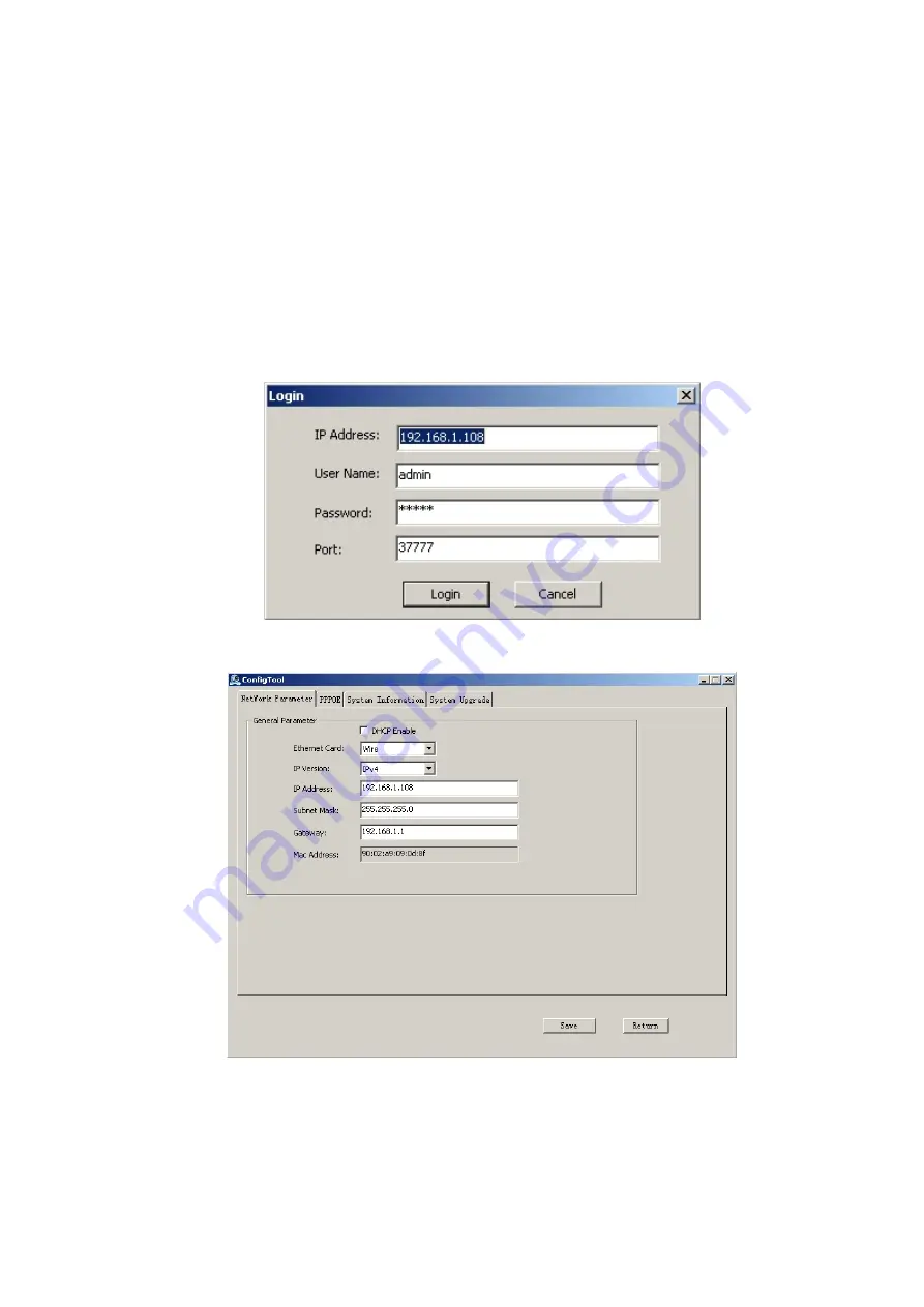
button to go to the login interface. See Figure 3-3. 
In Figure 3-3, you can view device IP address, user name, password and port. Please modify the 
corresponding information to login.  
Please note the port information here shall be identical with the port value you set in TCP port in Web 
Network interface. Otherwise, you cannot login the device.  
If you are using device background upgrade port 3800 to login, other setups are all invalid.  
After you logged in, the configuration tool main interface is shown as below. See Figure 3-4. 


Figure 3-3 Login prompt 


Figure 3-4 Main interface 

For detailed information and operation instruction of the quick configuration tool, please refer 
to the

 Quick Configuration Tool User’s Manual

 included in the resources CD. 


Summary of Contents for K-EF134L01E

Page 1: ...HD IR Vari focal Dome Network Camera Quick Start Guide Model No K EF134L01E Version 1 0 0...

Page 2: ...y or responsibility for all the fires or electrical shock caused by improper handling or installation We are not liable for any problems caused by unauthorized modification or attempted repair 2 Envir...

Page 3: ...sh or hair dries to remove it gently Stained with grease or fingerprint Use soft cloth to wipe the water drop or oil gently to make it dry then use oil free cotton cloth or paper soaked with alcohol o...

Page 4: ...open the package and check all the components are included Contact your local retailer ASAP if something is broken in your package Accessory Name Amount Network Camera Unit 1 Quick Start Guide 1 Insta...

Page 5: ...1 1 1 Components 1 1 2 Framework and Dimension 2 2 Device Installation 3 2 1 Installation Steps 3 3 Quick Configuration Tool 5 3 1 Overview 5 3 2 Operation 5 4 Web Operation 7 4 1 Network Connection...

Page 6: ...1 Figure 1 1 Component structure Please refer to the following sheet for detailed information Component Component Name Component 1 Dome body Component 2 Dome enclosure Port Port Name Note Port 3 Inter...

Page 7: ...2 1 2 Framework and Dimension Please refer to the following two figures for dimension information The unit is mm See Figure 1 2 Figure 1 2 Dimension illustration...

Page 8: ...Please follow the steps listed below to install the device Please refer to Figure 2 1 for reference Step 1 Use inner hex wrench in the accessories bag to open dome enclosure by unfastening three inne...

Page 9: ...adjusting lens horizontal direction to designated position Loosen two hand screws on both sides of fixed rotating bracket Loosen only do not take it down hold the camera module body with hand making...

Page 10: ...p 1 Double click the ConfigTools exe icon you can see an interface is shown as in Figure 3 In the device list interface you can view device IP address port number subnet mask default gateway MAC addre...

Page 11: ...s user name password and port Please modify the corresponding information to login Please note the port information here shall be identical with the port value you set in TCP port in Web Network inter...

Page 12: ...PC and the network camera respectively Network camera default IP address is 192 168 0 10 Subnet mask is 255 255 255 0 Gateway is 192 168 0 1 Use order ping network camera address to check connection i...

Page 13: ...ou can see the main window Please refer to the Web Operation Manual included in the resource CD for detailed operation instruction Note This quick start guide is for reference only Slight difference m...

Reviews: