19
9
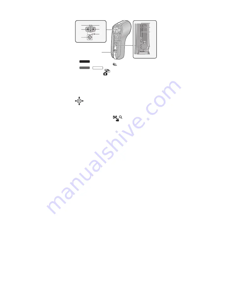
Slow Motion Mode button [
]
/
Zoom range button [
]
10
Photoshot button [
]
11
SET button [SET]
Use the SET button to select the recording functions and playback
operations, and to operate the menu screen.
In this owner’s manual, the operation of the SET button is denoted as
shown below.
Example:
12
In Recording Mode: Zoom button [W/T]
In Playback Mode: Volume button
Zoom button [W/T]
Thumbnail display switch [
/
]
13
Recording start/stop button [
]
14
Menu button [MENU]
15
Rear door
16
Card slot
17
Battery holder
18
HDMI micro connector
19
USB/AV connector
Use the USB cable/AV cable (only the supplied cable).
or
Select using the SET button
MENU
14
9
10
11
12
19
18
17
16
15
13
HX-WA30
HX-WA3
HX-WA03
●
●
●
Summary of Contents for HX-WA03PP
Page 9: ...9 3 5 Formatting ...
Page 11: ...11 4 Specifications ...
Page 12: ...12 ...
Page 13: ...13 ...
Page 14: ...14 ...
Page 15: ...15 ...
Page 16: ...16 ...
Page 17: ...17 ...
Page 21: ...21 6 Troubleshooting Guide 6 1 Confirmation Flow of Waterproof ...
Page 22: ...22 6 2 Airtight Inspection with Air Leak Tester ...
Page 23: ...23 6 3 Air Leak Tester RFKZ0528 Operating Instruction ...
Page 24: ...24 ...
Page 25: ...25 ...
Page 26: ...26 ...
Page 27: ...27 7 Service Fixture Tools ...
Page 30: ...30 8 3 1 Removal of the Top Ornament Fig D1 8 3 2 Removal of the Front Cabinet Unit Fig D2 ...
Page 31: ...31 8 3 3 Removal of the Side L Cabinet Unit Fig D3 Fig D4 ...
Page 32: ...32 Fig D5 Fig D6 8 3 4 Removal of the Battery Cover Fig D7 ...
Page 33: ...33 Fig D8 8 3 5 Removal of the Waterproof Rubber Fig D9 Fig D10 ...
Page 36: ...36 Fig D16 8 3 10 Removal of the Lens Holder Fig D17 8 3 11 Removal of the Speaker Fig D18 ...
Page 37: ...37 8 3 12 Removal of the LCD Unit with Case Fig D19 Fig D20 ...
Page 38: ...38 Fig D21 Fig D22 ...
Page 39: ...39 Fig D23 8 3 13 Removal of the Hinge Cover LCD Case T Unit Fig D24 Fig D25 ...
Page 40: ...40 Fig D26 Fig D27 8 3 14 Removal of the LCD O Ring Fig D28 ...
Page 41: ...41 Fig D29 8 3 15 Removal of the LCD Panel Fig D30 ...
Page 42: ...42 Fig D31 8 3 16 Removal of the Built in Micro phones Monitor P C B Fig D32 ...
Page 43: ...43 Fig D33 Fig D34 ...
Page 44: ...44 8 3 17 Removal of the LCD Hinge Unit Fig D35 Fig D36 ...
Page 45: ...45 Fig D37 8 3 18 Removal of the Switch Unit Fig D38 ...
Page 46: ...46 Fig D39 Fig D40 ...
Page 49: ...49 10 Maintenance 10 1 Regular Maintenance Flow ...


