background image

37

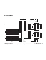
Fig. E2 Rough image of set-up connection

Part Number of jig

• Only a necessary jig mentions it in setup of electric adjustment.

Ref

Parts Name

Parts No.

Q'ty

Remarks

1

Personal Computer

---

1

With Tatsujin Software.

2

AC Adaptor

---

1

The AC Adaptor for High Definition Video Camera

3

DC Cable

---

1

The AC Adaptor for High Definition Video Camera

4

USB Cable

---

1

5

Step Up Ring

VFK1164TAR37

1

6

TATSUJIN PC-Adjustment Program

---

1

Summary of Contents for HDCSX5P - HD VIDEO CAMERA

Page 1: ...ized copying and distribu tion is a violation of law ORDER NO VM0708044CE B17 High Definition Video Camera Model No HDC SX5P HDC SX5PC HDC SX5EG HDC SX5E HDC SX5EB HDC SX5EP HDC SX5EE HDC SX5GC HDC SX...

Page 2: ...re for Removing Disc 11 4 Specifications 12 5 Location of Controls and Components 13 6 Service Mode 15 6 1 Error Display 15 6 2 Service Menu 16 7 Service Fixture Tools 18 8 Disassembly and Assembly In...

Page 3: ...t the customer from being exposed to shock hazards 1 1 1 Leakage Current Cold Check 1 Unplug the AC cord and connect a jumper between the two prongs on the plug 2 Measure the resistance value with an...

Page 4: ...exposure of the assembly 3 Use only a grounded tip soldering iron to solder or unsolder ES devices 4 Use only an antistatic solder removal device Some solder removal devices not classified as can gen...

Page 5: ...must not be used until a replacement cover is obtained A replacement fuse cover can be purchased from your local Panasonic Dealer If the fitted moulded plug is unsuitable for the socket outlet in you...

Page 6: ...is used Definition The letter of PbF is printed on the PCB using the lead free solder To put lead free solder it should be well molten and mixed with the original lead free solder Remove the remainin...

Page 7: ...st never be subjected to excessive heat or discharge It must therefore only be fitted in equipment designed specifically for its use Replacement batteries must be of the same type and manufacture They...

Page 8: ...8 2 5 How to Recycle the Lithium Battery U S Only...

Page 9: ...C B and Sub P C B 2 The following category are recycle module part Please send them to Central Repair Center Main P C B VEP03H39B HDC SX5EG E EP EB VEP03H39C HDC SX5GC SG VEP03H39D HDC SX5P PL VEP03H3...

Page 10: ...ged by Tatsujin kit according to the Movie Camera s suf fix Then confirm and or adjust the Camera section one by one 3 2 2 How to Discharge the Capacitor on the Flash P C B Remove the Flash P C B Refe...

Page 11: ...rmal product the disc cannot be removed while the ACCESS indicator is lit or blinking 3 3 2 Procedure for Removing the disc manually Please removing the disc by the following procedure when the disc c...

Page 12: ...12 4 Specifications...

Page 13: ...13 5 Location of Controls and Components Followings are the Location of Controls and Components for HDC SX5P PC as a sample For other models refer to each Operation Instructions...

Page 14: ...14...

Page 15: ...15 6 Service Mode 6 1 Error Display is displayed automatically on the EVF or the LCD Monitor when an undesirable condition has occurred...

Page 16: ...LETE button and LEFT of CURSOR button and AUTO MANUAL FOCUS switch to FOCUS button simulta neously for 3 seconds 3 Operating automatic diagnosis code is displayed Item 4 is selected with the UP or DOW...

Page 17: ...he error code clear after repair completion CLEAR METHOD If the SD card and disc inserted take out it before Service Menu operation Set mode dial to DISC RECORDING MODE of HD mode Pushed DELETE button...

Page 18: ...01 Sub Extension Cable 60pin LSUA0059 1 PS6905 Main DVD Drive Unit Extension Cable 50pin RFKZ0446 1 PS6004 Main CCD Extension Cable 40pin RFKZ0379 1 PS6003 Main PP4001 Jack Extension Cable 20pin VFK20...

Page 19: ...embly Instructions 8 1 Disassembly Flow Chart This flow chart indicates the disassembly steps the cabinet parts P C B and Mecha Unit in order to access to be serviced When reinstalling perform the ste...

Page 20: ...20 8 2 P C B Layout Fig F1...

Page 21: ...ctor P2403 DVD Drive Unit 7 EVF B L P C B Fig D13 1 Screw T 2 Screws U 1 Connector FP602 EVF Unit Fig D14 1 Screw V 1 Tab Eye Cap Unit Fig D15 2 Tabs EVF Cover 4 Tabs Slide Holder Fig D16 2 Screws W H...

Page 22: ...22 Fig D1 Fig D2 Fig D3 Fig D4...

Page 23: ...23 Fig D5 Fig D6...

Page 24: ...24 Fig D7 Fig D8 Fig D9...

Page 25: ...25 Fig D10 Fig D11 Fig D12 Fig D13...

Page 26: ...26 Fig D14 Fig D15 Fig D16 Fig D17...

Page 27: ...27 Fig D18 Fig D19 Fig D20 Fig D21...

Page 28: ...28 Fig D22 Fig D23 Fig D24 Fig D25...

Page 29: ...29 Fig D26 Fig D27 Fig D28 Fig D29...

Page 30: ...30 Fig D30 Fig D31 Fig D32 Fig D33...

Page 31: ...Unit The following flowchart describes order or steps for removing the Camera lens unit and certain printed circuit boards in order to make access to the item needing service To reassemble the unit fo...

Page 32: ...ments and Adjustments 9 1 Service Positions 9 1 1 List of the extension cables Use the following extension cables when checking or adjusting individual circuit boards except module Parts Main P C B an...

Page 33: ...33 9 1 2 Checking and repairing individual circuit boards except module part Main P C B and Sub P C B How to use extension cables...

Page 34: ...34 9 2 Location for Connectors of the Module P C B Main P C B and Sub P C B 9 2 1 Main P C B...

Page 35: ...35 9 2 2 Sub P C B...

Page 36: ...2 Set up manual for High Definition Video Camera Pay attention because the adjustment method is different from this machine 1 Save the software Install the effective model s TATSUJIN Software to PC Pe...

Page 37: ...electric adjustment Ref Parts Name Parts No Q ty Remarks 1 Personal Computer 1 With Tatsujin Software 2 AC Adaptor 1 The AC Adaptor for High Definition Video Camera 3 DC Cable 1 The AC Adaptor for Hi...

Page 38: ...red model 4 Turn on the camcorder Then click Fig E3 2 5 The communication is complete and the dialog will appear Then click to save the EEPROM data Fig E3 3 6 Saving for EEPROM data is complete menu w...

Page 39: ...3 4 Initial guideline The table below shows which adjustments are necessary according to the unit parts and individual parts to be replaced Make sure to perform these adjustments shown below as neces...

Page 40: ...procedure put a few droplets of absolute alcohol in a soft and dry cloth and use it to lightly clean the disc from the inner to outer edges in axial direction 10 3 Cleaning optical pickup 1 Attach the...

Page 41: ...41...

Page 42: ...Side S 37 S6 Replacement Parts List S 39 S7 Exploded View S 49 S7 1 Frame and Casing Section 1 S 49 S7 2 Frame and Casing Section 2 S 50 S7 3 LCD Section S 51 S7 4 Camera Lens Section S 52 S7 5 EVF S...

Page 43: ...4 8 4 8 4 8 IC601 25 2 5 2 5 2 5 IC601 26 2 5 2 5 2 5 IC601 27 2 5 2 5 2 5 IC601 28 0 0 0 IC601 29 4 5 4 5 4 5 IC601 30 4 3 4 3 4 3 IC601 31 0 7 0 7 0 7 IC601 32 0 4 0 4 0 4 IC601 33 4 8 4 8 4 8 IC601...

Page 44: ...2 4 2 4 2 S2 6 Front P C B REF No PIN No REC PB EE IC481 1 1 3 1 3 1 3 IC481 2 0 0 0 IC481 3 3 3 3 IC481 4 1 2 1 2 1 2 IC482 1 1 3 1 3 1 3 IC482 2 0 0 0 IC482 3 3 3 3 IC482 4 1 2 1 2 1 2 Q491 E 3 4 3...

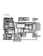
Page 45: ...ROM IC3501 H 264 VIDEO CODEC AC3 AUDIO CODEC IC3400 MPEG JPEG VIDEO AUDIO CODEC USB 2 0 I F SD I F ATAPI I F IC3300 ONIKISS VIDEO SIGNAL PROCESSOR AUDIO SIGNAL PROCESSOR VIDEO AUDIO STREAM CONTROL IC...

Page 46: ...ND D GND D GND MIC GND IROUT LENSBA CLOSE LENSBA OPEN SENS SW STORM HD S SCK LEN S SDO LEN STORM VD STORM LVD LENS RST LEN S SDI LEN S NSCS LEN PINTRV LEN ZABS LEN FABS LEN FNO LEN MREF LEN LEDCONT LE...

Page 47: ...B G E G PW LCD8R5V CLK2 E CKH1 CLK2 E CKH2 D GND EVF SLIDE SW 22 G HMIC L 23 21 20 19 18 17 S CLK SHDECLK MIC GND S SDA SHDE SHDE DET G HMIC R MIC GND 29 PW SHDENOREG 30 PW SHDENOREG 31 28 27 26 25 2...

Page 48: ...0A 8176 8176 8 5 4 1 10 75 A5 6 75 A5 6 4 A 6 A5 4 75 A5 29A5 4 8 29A5 4 8 A 0 A 0 A 0 A 0 A 0 A 0 A 0 A 0 A 0 A 0 A 0 A 0 6 2A 6 A 66 A75 A A75 A 4 A241 75 A5 6 75 A5 6 8 75 8 75 176 176 0 0 0 0 A2...

Page 49: ...5 6 3 5 5 0 4 75 A5 6 75 A5 6 75 A5 75 A5 6 75 A5 6 29A5 4 8 4 A5 4 75 A5 6 75 A5 6 75 A5 6 75 A5 6 75 A5 29A5 4 84 4 A 6 4 A241 5 4 100 614 8 8 0 0 0 0 0 6 92 61 8 1 61 219 4 HDC SX5 Series SD Holder...

Page 50: ...75 A5 7 0 A59 219 4A A59 114A12 0A59 61 52 4 4 761 0 4 5 6 61 10 614 8 A 61 10 55 61 10 55 61 10 614 61 10 614 61 219 4 61 8 A 29A5 1 014 29A5 1 014 29A5 1 014 29A5 1 014 5A5 A5 1 5A5 A5 1 5A A5 1 5 1...

Page 51: ...8 29A 8 A 0 A A4 A A 3 5 3 5 4 4 29A 4 8A A A A A A A A A A A A A 5A 6A A 5A A A 5A A 8 8 8 8 8 8 8 8 6 4 5 6 0 0 0 0 0 1 5 0 56 56 2 2 0 56 8 0 0 8 56 5 6 5 568 568 61 10 55 61 10 55 5 5 8 6 56 6 56...

Page 52: ...4 A A 29A 4 8A 4 A4A176 A A176 A A176 A 0 A568 A 1 61 5 A4 5 5 29A 4 8 A56 61 2 0 5 8 855 56 8 5 0 58 568 8 1 0 A A A A A 5 29A 8 A 8 A 0 A 0 HDC SX5 Series EVF B L Schematic Diagram 10 9 8 7 6 5 4 3...

Page 53: ...A A A A A4 A A 29A 4 8A A A A A 4 A 58 29A 4 8 A A A 5 A56 A 5 A 106 A 1 A A A5 A568 A A4 5 5 1 5 0 88 568 58 8 0 8 8 855 5 56 A A A 0 A A A 8 29A 8 29A 8 A 0 A 0 A 0 A 0 61 5 A4 61 2 0 5 HDC SX5 Seri...

Page 54: ...4 4 4 4 4 4 4 4 4 5 3 0 2 2 0 4 4 A 0 R W R 2 2 8 8 29A4 8 A176A4 A 0 A 0 A 0 A176A A176A4 A176A 61 A 2 HDC SX5 Series Mic Schematic Diagram 10 9 8 7 6 5 4 3 2 1 G F E D C B A S4 8 Mic Schematic Diag...

Page 55: ...12 A 41 29A4 8 29A4 8 29A4 8 29A4 8 29A4 8 6 4176 4 1 10 A176A4 A176A4 A176A A176A 05 A12 0 05 A 15 A 0 A 0 A 0 05 A2 05 A2 05 A 05 A A 412 05 A 4 A 41 29A4 8 29A4 8 29A4 8 176 176 176 8 8 8 0 0 0 84...

Page 56: ...05 A12 0 A 0 29A4 8 29A4 8 5 64A 15 16 4A2 16 4A2 16 4A2 5 64A12 0 5 64A 12A5 6 4A A5 6 4A 5 6 4A12 0 5 6 4A 15 16 4A 16 4A 16 4A A 0 HDC SX5 Series Lens BA Section Front P C B 2 2 Schematic Diagram...

Page 57: ...4 4 3 2 2 3 5 3 5 3 2 3 25 8 2 5 2 2 6 34 704 34 704 6 6 56A014 56A014 56A014 0 4 64 0 A 0 A 0 A 0 A 0 29A4 8 29A4 8 010A 010A 64 HDC SX5 Series Flash Schematic Diagram 10 9 8 7 6 5 4 3 2 1 G F E D C...

Page 58: ...6 A 6 A 6 A 6 A 6 A 6 A 6 A 6 A 6 A 6 A 6 A 6 A94 6 A94 6 A 14 6 A 14 6 A 0643 6 A 0643 A 8 A 8 A 8 A 8 A 8 A 8 52 52 A 0 A 0 A 0 A 0 A 0 A 0 7 46 7 46 7 461 7 461 8 8 8 8 8 8 48A A5 1 48A A5 1 8 8 8...

Page 59: ...62 62 62 66A 29A 66A 66A 6 66A HDC SX5 Series Battery Schematic Diagram HDC SX5 Series LCD DET Schematic Diagram 10 9 8 7 6 5 4 3 2 1 G F E D C B A S4 13 LCD DET Schematic Diagram S4 14 Battery Schem...

Page 60: ...S 19...

Page 61: ...S 20 0 0 8 8 8 8 8 8 4 4 4 A5 A3 A5 A A5 4A3 A5 4A 4 8 4 4 8 4 4 4 4 8 8 8 8 81 81 0 0 26 26 8 8 HDC SX5 Series CCD FPC Schematic Diagram 1 4 N M L K J I H G S4 15 CCD FPC Schematic Diagram S 20...

Page 62: ...8 4 8 4 5 3 A5 A 4 8 8 8 8 4 4 8 4 8 4 4 8 4 8 8 81 81 0 0 26 26 26 26 8 8 0 0 0 0 0 4 0 4 0 4 0 4 A5 8 8 8 4 29A 8 4 57 29A 8A4 29A 8A4 4 29A 84 A5 4 29A 8A 29A 8A 8 4 8 4 8 4 8 8 HDC SX5 Series CCD...

Page 63: ...4 4 4 4 4 4 4 3 3 57 4 4 4 57 4 8 4 8 4 8 4 A5 A5 A3 A5 A A5 4A3 A5 4 A5 4A 4 8 8 8 8 4 4 8 4 4 4 4 857 857 8 8 8 8 81 81 0 0 26 26 8 8 8 8 8 8 8 8 HDC SX5 Series CCD FPC Schematic Diagram 11 10 9 8...

Page 64: ...4 8 4 8 4 4 4 8 8 8 8 8 8 8 8 4 857 8 8 81 81 0 0 26 26 26 26 8 8 8 8 8 8 8 8 0 0 0 0 0 4 0 4 0 4 0 4 0 4 0 4 0 4 0 4 A5 8 8 8 4 29A 8 4 57 A5 29A 8A4 29A 8A4 57 4 4 4 29A 84 A5 4 29A 8A 29A 8A 8 4 8...

Page 65: ...S 24 S5 Print Circuit Board S5 1 Jack P C B 5 4 4 4 4 3 4 4 22 HDC SX5 Series Jack P C B Component Side 10 9 8 7 6 5 4 3 2 1 G F E D C B A Component Side S5 1 1 Jack P C B Component Side...

Page 66: ...S 25 4 4 4 4 4 4 4 4 4 6 4 4 4 4 8 8 8 HDC SX5 Series Jack P C B Foil Side 10 9 8 7 6 5 4 3 2 1 G F E D C B A Foil Side S5 1 2 Jack P C B Foil Side...

Page 67: ...S 26 5 8 8 8 8 8 5 5 5 5 4 4 4 4 4 4 4 4 HDC SX5 Series Side R P C B Component Side 10 9 8 7 6 5 4 3 2 1 G F E D C B A Component Side S5 2 Side R P C B S5 2 1 Side R P C B Component Side...

Page 68: ...S 27 8 4 4 8 8 8 8 8 8 4 4 4 4 4 4 4 4 4 4 4 4 4 4 4 4 4 4 4 4 4 3 3 2 2 2 2 HDC SX5 Series Side R P C B Foil Side 10 9 8 7 6 5 4 3 2 1 G F E D C B A Foil Side S5 2 2 Side R P C B Foil Side...

Page 69: ...S 28 2 2 4 4 3 4 HDC SX5 Series EVF B L P C B 10 9 8 7 6 5 4 3 2 1 G F E D C B A Foil Side Component Side S5 3 EVF B L P C B...

Page 70: ...S 29 HDC SX5 Series Monitor P C B Component Side 10 9 8 7 6 5 4 3 2 1 G F E D C B A Component Side S5 4 Monitor P C B S5 4 1 Monitor P C B Component Side...

Page 71: ...S 30 2 4 4 4 4 4 4 4 4 4 4 3 3 3 3 3 2 HDC SX5 Series Monitor P C B Foil Side 10 9 8 7 6 5 4 3 2 1 G F E D C B A Foil Side S5 4 2 Monitor P C B Foil Side...

Page 72: ...S 31 4 2 2 8 8 4 4 4 4 4 4 4 4 4 3 HDC SX5 Series Mic P C B 10 9 8 7 6 5 4 3 2 1 G F E D C B A Foil Side Component Side S5 5 Mic P C B...

Page 73: ...S 32 4 4 4 4 4 4 4 4 4 4 34 34 3 3 2 2 2 4 4 4 34 3 4 HDC SX5 Series Front P C B 10 9 8 7 6 5 4 3 2 1 G F E D C B A Foil Side Component Side S5 6 Front P C B...

Page 74: ...S 33 4 3 4 4 4 34 3 4 4 4 4 3 4 4 6 6 2 4 34 4 4 3 3 4 4 4 6 2 25 HDC SX5 Series Flash P C B 10 9 8 7 6 5 4 3 2 1 G F E D C B A Foil Side Component Side S5 7 Flash P C B...

Page 75: ...S 34 25 22 HDC SX5 Series Drive Extend P C B 10 9 8 7 6 5 4 3 2 1 G F E D C B A Foil Side Component Side S5 8 Drive Extend P C B...

Page 76: ...S 35 62 62 62 5 1 2 0 0 HDC SX5 Series Battery P C B HDC SX5 Series LCD DET P C B Foil Side Component Side 10 9 8 7 6 5 4 3 2 1 G F E D C B A Foil Side S5 9 LCD DET P C B S5 10 Battery P C B...

Page 77: ...S 36 HDC SX5 Series CCD FPC P C B Component Side 10 9 8 7 6 5 4 3 2 1 G F E D C B A Component Side S5 11 CCD FPC P C B S5 11 1 CCD FPC P C B Component Side...

Page 78: ...S 37 22 4 4 4 4 4 4 3 4 4 4 4 4 4 3 4 4 4 4 4 4 3 HDC SX5 Series CCD FPC P C B Foil Side 10 9 8 7 6 5 4 3 2 1 G F E D C B A Foil Side S5 11 2 CCD FPC P C B Foil Side...

Page 79: ...S 38...

Page 80: ...resistors are in OHMS K 1 000 OHMS All capacitors are in MICRO FARADS uf P uuF Components identified with the mark have the special characteristics for safety When replacing any of these components u...

Page 81: ...ACITOR CH 4V 47U 1 B4001 ML 614S ZT BATTERY 1 C604 F1G0J1050007 C CAPACITOR CH 6 3V 1U 1 C605 F1G1C104A080 C CAPACITOR CH 16V 0 1U 1 C3901 F1G0J1050007 C CAPACITOR CH 6 3V 1U 1 C606 F1G1C104A080 C CAP...

Page 82: ...1 16W 22 1 R6310 ERJ2GEJ473Y M RESISTOR CH 1 16W 47K 1 R904 D0YAR0000007 M RESISTOR CH 1 16W 0 1 R6311 ERJ2GEJ102X M RESISTOR CH 1 16W 1K 1 R905 D0YAR0000007 M RESISTOR CH 1 16W 0 1 R6312 ERJ2GEJ472...

Page 83: ...VEP22384A DRIVE EXTENDED P C B RTL L481 G1C100KA0115 CHIP INDUCTOR 10UH 1 PP6998 K1KA60A00145 CONNECTOR 60P 1 P6701 K1MN10BA0197 CONNECTOR 10P 1 PS6999 K1KY60AA0384 CONNECTOR 60P 1 Q491 B1ABCF000098 T...

Page 84: ...RS 1 13 VMG1808 FAN DAPER RUBBER 1 14 EFN MVW76ZC FLASH U 1 15 VYQ4105 BOTTOM FRAME U 1 16 VEP23672A JACK P C B 1 RTL 17 VGQ9673 RADIATION SHEET BOTTOM 1 18 N9ZZ00000377 SIDE CASE L U 1 19 LSXY1076 DI...

Page 85: ...GHT 1 53 VGK3358 LENS DECORATION 1 54 VSC6000 EARTH PLATE R 1 55 VMG1705 LENS DAMPER RUBBER 1 56 N9ZZ00000326 BARRIER MOTOR UNIT 1 57 VDW1233 2 FRONT FRAME 1 58 VML3925 1 BARRIER SELECT KNOB 1 61 VYK2...

Page 86: ...VGQ9584 LIGHTING PLATE HOLDER 1 205 VGL1253 PRISM SHEET A 1 206 VGL1254 PRISM SHEET B 1 207 VGL1255 DIFFUSION SHEET 1 208 VKW3365 LIGHTING PLATE 1 209 VGL1256 REFLECTION SHEET 1 210 VEP26301A MONITOR...

Page 87: ...3 VXQ1534 OIS U 1 302 4 VXP2780 IRIS U 1 302 5 L6HA64NC0003 ZOOM MOTOR U 1 302 6 L6HA66NC0012 STEPPING MOTOR 1 302 7 VMS7638 GUIDE POLE 1 302 8 VMS7638 GUIDE POLE 1 302 9 VXP2531 4TH LENS FRAME MOVE...

Page 88: ...1 410 VGQ9121 BL PIECE 1 411 VMP8920 EVF FRAME 1 412 VEP29194A EVF B L P C B 1 RTL 413 VGQ9575 EYE CUP 1 414 VGQ9579 EVF COVER 1 415 VGQ9578 EVF REINFORCEMENT PIECE 1 416 VGQ9118 LCD HOLD PIECE 1 417...

Page 89: ...C 509 VFF0386 S CD ROM 1 P PC 510 VQT1G53 O I GE 1 EG 510 VQT1G54 O I FR 1 EG 510 VQT1G55 O I IT 1 EG 510 VQT1G56 O I DU 1 EG 510 VQT1G57 O I TK 1 EG 510 VQT1G58 O I PR 1 E 510 VQT1G59 O I SP 1 E 510...

Page 90: ...B43 B42 B44 B5 B4 B38 B33 B32 B45 B2 B1 B57 B47 B25 B46 B27 B56 B48 B28 B3 B29 1 27 21 RTL BATTERY P C B 20 26 B37 25 22 24 23 3 RTL SUB P C B 74 6 75 76 80 79 83 14 78 77 11 8 12 13 84 81 82 2 RTL MA...

Page 91: ...MIC P C B 69 53 57 55 51 52 50 B40 B41 B19 B23 B24 B53 71 RTL FRONT P C B B22 87 58 56 B54 B55 54 70 B20 B21 31 RTL SIDE R P C B B8 B14 B11 B7 B9 B26 B17 B15 B16 B10 B6 B34 B35 B52 B36 B12 B13 49 33...

Page 92: ...S7 3 LCD Section S 51 201 218 211 203 204 206 205 207 208 209 210 RTL MONITOR P C B 215 B201 B202 214 213 212...

Page 93: ...S7 4 Camera Lens Section S 52 B39 B315 B314 B308 B313 B312 B311 B306 B307 B302 B303 B301 B304 B305 88 301 1 301 2 301 73 303 302 302 10 302 9 302 3 302 6 302 4 302 1 302 7 302 8 302 2 302 5...

Page 94: ...S7 5 EVF Section S 53 413 405 404 407 406 B405 B402 B401 B407 B408 414 423 411 B404 B403 402 403 415 401 B406 419 417 420 416 408 418 421 422 409 410 412 RTL EVF B L P C B 424...

Page 95: ...S7 6 Packing Parts and Accessories Section S 54 504 507 502 506 503 Battery Pack Unit 512 508 513 511 509 510 505 GN 505 505 505 EB GC GCS SG E EG EP GC GCS SG EE 505 GK P PC PL...

Reviews: