


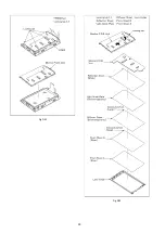


20
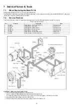
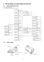
7 Service Fixture & Tools
7.1.
When Replacing the Main P.C.B.
After replacing the MAIN P.C.B., be sure to achieve adjustment.
The adjustment instruction is available at “software download” on the “Support Information from NWBG/VDBG-AVC” web-site in
“TSN system”, together with Maintenance software.
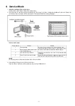
7.2.
Service Position
This Service Position is used for checking and replacing parts. Use the following Extension cables for servicing.
Table S1 Extension Cable List
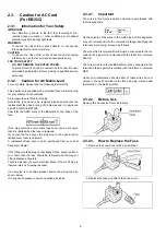
CAUTION-1. (When servicing FLASH P.C.B.)
1. Be sure to discharge the capacitor on FLASH P.C.B..
Refer to “HOW TO DISCHARGE THE CAPACITOR ON FLASH P.C.B.”.
The capacitor voltage is not lowered soon even if the AC Cord is unplugged or the battery is removed.
2. Be careful of the high voltage circuit on FLASH P.C.B..
3. DO NOT allow other parts to touch the high voltage circuit on FLASH P.C.B..
No.
Parts No.
Connection
Form
1
VFK1933
PP6003(MAIN) - PS6701(POWER FPC)
34PIN 0.5 B to B
2
RFKZ0448
FP6008(MAIN) - LENS UNIT
33PIN 0.3 FPC
3
VFK1933
PP6004(MAIN) - MONITOR FPC
34PIN 0.5 B to B
4
RFKZ0343
PP6002(MAIN) - PS7001(FLASH)
30PIN 0.5 B to B
5
RFKZ0379
PS6002(MAIN) - PP6401(SD)
40PIN 0.5 B to B
6
VFK1480
FP6001(MAIN) - FP6501(SIDE (R) OP)
6PIN 0.5 FFC
7
VFK1286
FP7001(FLASH) - FRONT CASE UNIT
16PIN 0.5 FFC
Summary of Contents for HDC-TM55EB
Page 10: ...10 3 5 Formatting...
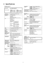
Page 11: ...11 4 Specifications...
Page 12: ...12...
Page 13: ...13...
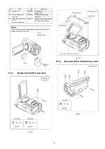
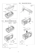
Page 24: ...24 Fig D4 8 3 3 Removal of the ESD P C B Unit Fig D5 8 3 4 Removal of the Top Case Fig D6...
Page 30: ...30 Fig D22 Fig D23...
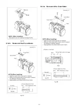
Page 33: ...33 Fig D30 8 3 23 Removal of the Focus Motor Fig D31 8 3 24 Removal of the Zoom Motor Fig D32...
Page 66: ...S7 3 LCD Section S 27 B7 B8 26 27 28 25 29 22 18 30 24 19...