12
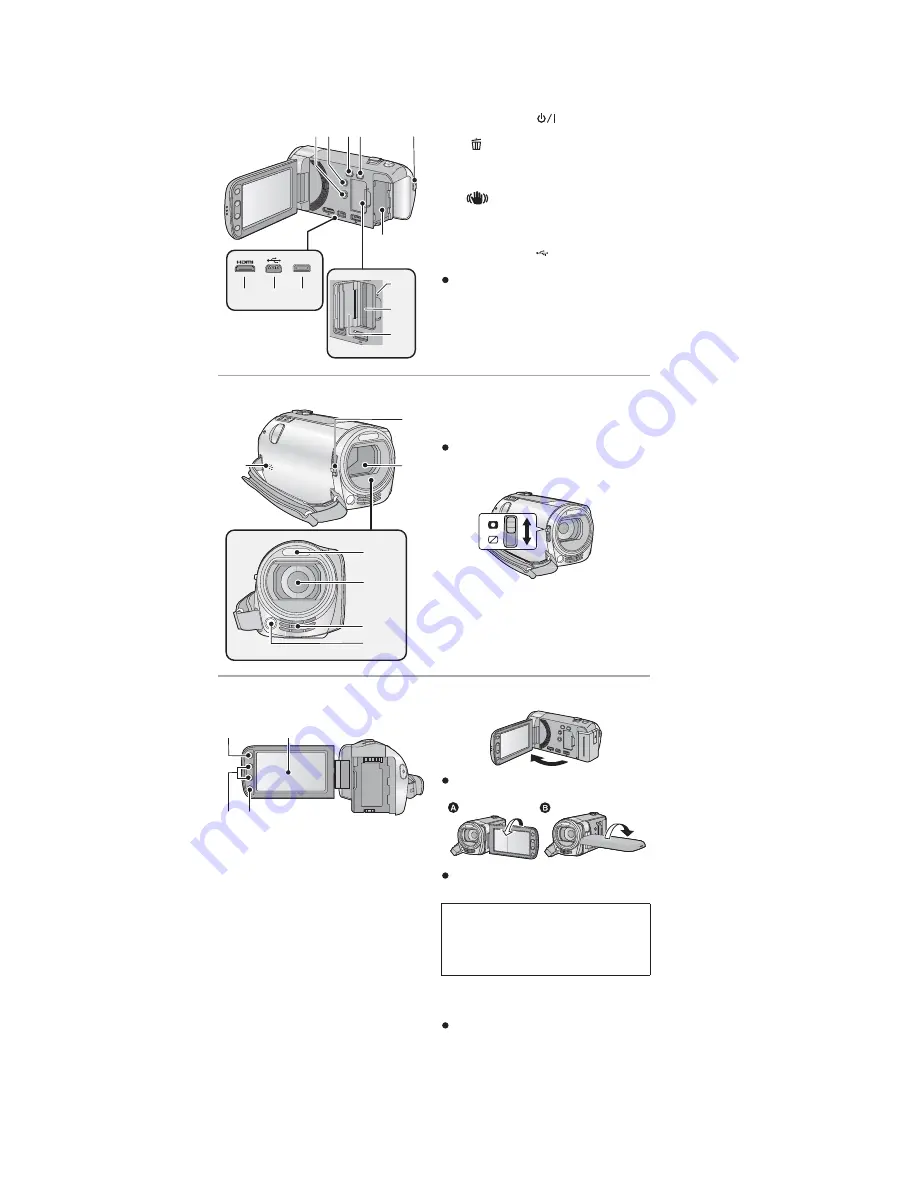
5 Location of Controls and Components
1
Power button [
]
2
Delete/Video light button
[
/LIGHT]
3
Intelligent auto/Manual button
[iA/MANUAL]
4
Optical image stabilizer button
[
O.I.S.]
5
Recording start/stop button
6
Battery holder
7
HDMI mini connector [HDMI]
8
USB terminal [
]
9
AV multi connector [AV MULTI]
Use the AV multi cable (only the supplied
cable).
10 Access lamp [ACCESS]
11 Card slot
12 SD card cover
13 Speaker
14 Lens cover opening/closing switch
When not using the unit, close the lens
cover to protect the lens.
Slide the opening/closing switch to
open/close the cover.
15 Lens cover
16 Built-in flash
17 Lens
18 Internal stereo microphones
19 Video light
1 2 3 4
6
5
AV MULTI
12
7
8
9
10
11
13
17
16
19
15
14
18
20 LCD monitor (Touch screen)
It can open up to 90
Q
.
It can rotate up to 180
Q
towards the lens
or 90
Q
towards the opposite direction.
21 Menu button [MENU]
22 Adjust zoom buttons
23 Sub recording start/stop button
This button functions in the same manner
as the recording start/stop button.
20
22
21
23
Due to limitations in LCD production
technology, there may be some tiny bright
or dark spots on the LCD monitor screen.
However, this is not a malfunction and
does not affect the recorded picture.
Summary of Contents for HDC-SDX1EC
Page 10: ...10 4 Specifications ...
Page 11: ...11 ...
Page 21: ...21 Fig D4 8 3 3 Removal of the Front Case Unit Fig D5 ...
Page 22: ...22 Fig D6 8 3 4 Removal of the Flash P C B Unit Fig D7 8 3 5 Removal of the Lens Unit Fig D8 ...
Page 23: ...23 8 3 6 Removal of the Main P C B Unit and SD Holder P C B Unit Fig D9 Fig D10 ...
Page 24: ...24 8 3 7 Removal of the Zoom Switch Unit Fig D11 8 3 8 Removal of the Power FPC Unit Fig D12 ...
Page 26: ...26 FIg D16 Fig D17 ...
Page 28: ...28 8 3 13 Removal of the Focus Motor Fig D20 8 3 14 Removal of the Zoom Motor Fig D21 ...
Page 41: ...S 10 ...
Page 50: ...S 19 S7 3 LCD Section B24 19 20 18 17 23 22 21 16 15 14 B23 B25 29 ...


