background image

HDC-SD80P-K  vol.1

Ref.No.

Part No.

Part Name & Description

Pcs

Remarks

Ref.No.

Part No.

Part Name & Description

Pcs

Remarks


S6401

K0H1BA000580 SWITCH

1

      ##

VEP03J12BP

MAIN P.C.B. UNIT

1 (RTL)E.S.D.

S6402

K0H1BA000580 SWITCH

1

 SD80EB,EC,EF,EG,EP

S6403

K0H1BA000580 SWITCH

1

      ##

VEP03J12BQ

MAIN P.C.B. UNIT

1 (RTL)E.S.D.

S6404

K0F111A00475 SWITCHES FOR SMALL SIGNAL

1

 SD80EE,GC,GK,GN,GA


      ##

VEP03J12BN

MAIN P.C.B. UNIT

1 (RTL) E.S.D. SD80GT,P,PC

VA6403

D4ED18R00003 VARISTOR

1

      ##

VEP03J12AP

MAIN P.C.B. UNIT

1 (RTL) E.S.D.

VA6404

D4ED18R00003 VARISTOR

1

 TM80EBK,EC,EF,EG,EP


      ##

VEP03J12AQ

MAIN P.C.B. UNIT

1 (RTL) E.S.D.

ZB6401

K3ZZ00500014 BATTERY HOLDER

1

 TM80EE,GC,GK,GA


      ##

VEP03J12AN

MAIN P.C.B. UNIT

1 (RTL) E.S.D. TM80P,PC,PU


      ##

VEP03J16A

SD HOLDER P.C.B. UNIT

1 (RTL) E.S.D.


       ##

VEP03J16A

SD HOLDER P.C.B. UNIT

(RTL) E.S.D.


C3906

F1G1C104A077 C.CAPACITOR CH 16V   0.1U

1

C3907

F3G0J107A017 C.CAPACITOR CH 6.3V  100U

1

C3908

F1G1E1030005 C.CAPACITOR CH 25V  0.01U

1

C3909

F1G1C104A077 C.CAPACITOR CH 16V   0.1U

1

C3910

F1G1E1030005 C.CAPACITOR CH 25V  0.01U

1

C3911

F1G0J1050007 C.CAPACITOR CH 6.3V    1U

1

C6401

F1J1A106A043 C.CAPACITOR CH 10V    10U

1

C6403

F1G1C104A077 C.CAPACITOR CH 16V   0.1U

1

C6404

F1G1C104A077 C.CAPACITOR CH 16V   0.1U

1

C6405

F1G1C104A077 C.CAPACITOR CH 16V   0.1U

1

C6407

F1G1C104A077 C.CAPACITOR CH 16V   0.1U

1

C6408

ECJ1VB1A105K C.CAPACITOR CH 10V     1U

1

C6412

F1H1E105A116 C.CAPACITOR CH 25V     1U

1


D6451

B3AAB0000343 LED

1 E.S.D.


FP6402

K1MY10BA0370 CONNECTOR             10P

1


HS3901

K1NA09E00098 SD CARD SLOT

1


IC6401

EWTS9PSL11

IC

1 E.S.D.


IP6401

K5H4021A0011 IC PROTECTOR

1


JK6401

K2EBYB000003 JACK

1

JK6402

K2HZ105E0013 JK, USB

1


LB6401

J0JJC0000015 FILTER

1

LB6402

J0JJC0000015 FILTER

1


P6401

K1KA02BA0014 CONNECTOR              2P

1


PS6401

K1KB50AA0094 CONNECTOR             50P

1


Q3901

B1ADKB000015 TRANSISTOR

1 E.S.D.


QR6401

B1GDCFYY0010 TRANSISTOR

1 E.S.D.

QR6402

B1GDCFYY0010 TRANSISTOR

1 E.S.D.


R3901

ERJ2GEJ470

M.RESISTOR CH 1/16W    47

1

R3902

ERJ2GEJ560X M.RESISTOR CH 1/10W    56

1

R3903

ERJ2GEJ103

M.RESISTOR CH 1/10W   10K

1

R3904

ERJ2GEJ271

M.RESISTOR CH 1/10W   270

1

R3905

ERJ2GEJ331

M.RESISTOR CH 1/16W   330

1

R3906

ERJ2GEJ102Y M.RESISTOR CH 1/10W    1K

1

R3907

ERJ2GEJ102Y M.RESISTOR CH 1/10W    1K

1

R3909

ERJ2GEJ333

M.RESISTOR CH 1/16W   33K

1

R3910

D0GB150JA057 M.RESISTOR CH 1/10W    15

1

R6402

ERJ2GEJ222

M.RESISTOR CH 1/10W  2.2K

1

R6403

ERJ2GEJ102Y M.RESISTOR CH 1/10W    1K

1

R6405

ERJ2GEJ101

M.RESISTOR CH 1/10W   100

1

R6406

ERJ2GEJ302

M.RESISTOR CH 1/16W    3K

1

R6407

ERJ2GEJ392

M.RESISTOR CH 1/10W  3.9K

1

R6408

ERJ2GEJ223

M.RESISTOR CH 1/16W   22K

1

R6409

D1JBR084A023 FUSE RESISTOR

1

R6410

ERJ3GEY0R00 M.RESISTOR CH 1/10W     0

1


RX3901

D1H85604A024 RESISTOR NETWORKS

1

RX3902

EXB28V103JX RESISTOR NETWORKS

1


S-8

Summary of Contents for HDC-SD80EB

Page 1: ...27 High Definition Video Camera Model No HDC SD80P HDC SD80PC HDC SD80EB HDC SD80EC HDC SD80EE HDC SD80EF HDC SD80EG HDC SD80EP HDC SD80GA HDC SD80GC HDC SD80GN HDC SD80GK HDC SD80GT HDC TM80P HDC TM80PC HDC TM80PU HDC TM80EB HDC TM80EC HDC TM80EE HDC TM80EF HDC TM80EG HDC TM80EP HDC TM80GA HDC TM80GC HDC TM80GK ...

Page 2: ...3 3 Important Notice 1 Other than U S A and Canadian Market 7 3 4 How to Define the Model Suffix NTSC or PAL model 8 3 5 Formatting 9 4 Specifications 10 5 Location of Controls and Components 12 6 Service Mode 16 6 1 Built in Memory Self Check Execution HDC TM80 only 17 6 2 Lock Search History Indication 17 6 3 Power ON Self Check Result Display 18 6 4 Erasing the lock histories 18 6 5 Erasing the...

Page 3: ...exposed to shock hazards 1 2 Leakage Current Cold Check 1 Unplug the AC cord and connect a jumper between the two prongs on the plug 2 Measure the resistance value with an ohmmeter between the jumpered AC plug and each exposed metal lic cabinet part on the equipment such as screwheads connectors control shafts etc When the exposed metal lic part has a return path to the chassis the reading should ...

Page 4: ...ly a grounded tip soldering iron to solder or unsolder ES devices 4 Use only an antistatic solder removal device Some solder removal devices not classified as antistatic ESD protected can generate electrical charge sufficient to damage ES devices 5 Do not use freon propelled chemicals These can generate electrical charges sufficient to damage ES devices 6 Do not remove a replacement ES device from...

Page 5: ...must not be used until a replacement cover is obtained A replacement fuse cover can be purchased from your local Panasonic Dealer If the fitted moulded plug is unsuitable for the socket outlet in your home then the fuse should be removed and the plug cut off and disposed of safety There is a danger of severe electrical shock if the cut off plug is inserted into any 13 ampere socket If a new plug i...

Page 6: ...ed to excessive heat or discharge It must therefore only be fitted in requirement designed specifically for its use Replacement batteries must be of same type and manufacture They must be fitted in the same manner and location as the original battery with the correct polarity contacts observed Do not attempt to re charge the old battery or re use it for any other purpose It should be disposed of i...

Page 7: ...older Remove the remaining lead free solder on the P C B cleanly for soldering of the new IC Since the melting point of the lead free solder is higher than that of the normal lead solder it takes the longer time to melt the lead free solder Use the soldering iron more than 70W equipped with the temperature control after setting the temperature at 350 30 C 662 86 F Recommended Lead Free Solder Serv...

Page 8: ...s the difference is that the INITIAL SETTING data which is stored in Flash ROM mounted on Main P C B 3 4 1 Defining methods To define the model suffix to be serviced refer to the rating label and caution label which are putted on the Unit NOTE After replacing the MAIN P C B be sure to achieve adjustment The adjustment instruction is available at software download on the Support Information from NW...

Page 9: ...9 3 5 Formatting ...

Page 10: ...10 4 Specifications ...

Page 11: ...11 ...

Page 12: ...tect the lens Lens cover does not close automatically Slide the Lens cover closing switch to close the cover 10 Lens cover 11 LED light It can be used as a Video light or Photo light 12 Lens 13 Internal stereo microphones AV MULTI 1 3 4 5 8 6 7 2 9 11 12 13 10 14 Mode switch 15 Status indicator 16 Recording start stop button 17 LCD monitor Touch screen It can open up to 90Q It can rotate up to 180...

Page 13: ...hotoshot button 24 Zoom lever W T In Motion Picture Recording Mode or Still Picture Recording Mode Thumbnail display switch Volume lever UVOLT In Playback Mode 25 Grip belt Adjust the length of the grip belt so that it fits your hand Flip the belt Adjust the length Replace the belt 26 DC input terminal DC IN Do not use any other AC adaptors except the supplied one 3 2 4 2 25 26 ...

Page 14: ...select icon or picture Touch the centre of the icon Touching the touch screen will not operate while you are touching another part of the touch screen Slide while touching Move your finger while pressing on the touch screen Selecting a mode Motion picture recording mode Still picture recording mode Playback mode How to use the touch screen About the operation icons These icons are used to switch t...

Page 15: ...pages upward or downward Displayed only during the Manual Mode To display the Touch Menu Do not touch on the LCD monitor with hard pointed tips such as ball point pens Touch Menu Recording Mode Playback Mode The Touch Menu will disappear when no function is performed for a specific period of time during Recording Mode To display it again touch T W MENU T W FOCUS WB SHTR IRIS MENU ALL Perform the t...

Page 16: ...e When recorded data in Built in memory error display is done 3 Built in memory self check execution HDC TM80 only Function to check self as for the state of Built in memory 4 Lock search history indication Display the camera system error cord for three histories saved in EEPROM 5 Power ON self check result display Power ON self check function to diagnose correct function of the device and interfa...

Page 17: ...Search History Indication Touch the 4 of LCD select Lock search history indication Operation specifications Indication contents Lock search history indication Display the camera system error cord for three histories saved in EEPROM The error cord contents which are displayed Cutting of battery connection or AC power supply connection to end the service mode Error code Function 51 Focus control is ...

Page 18: ...nucation test result CAM PWR Commnucation test between IC2006 to IC1503 CAM UNI Commnucation test between IC2006 to IC3401 Display other than OK are abnomalities of each lines Cutting of battery connection or AC power supply connection to end the service mode 6 4 Erasing the lock histories Touch the 10 of LCD select erasing the lock histories execution Operation specifications Indication contents ...

Page 19: ...nal media management information is not required Case1 When replacing the flash memory chip IC3402 or replacing the MAIN P C B Unit Before checking the operations after replacing the parts erasing the internal media management information Case2 When replacing the ESD P C B Unit Before replacing the ESD P C B Unit erasing the internal media management information then replace it new one CAUTION Whe...

Page 20: ...the camera informations while playing back the recorded video Operation specifications Indication contents While playing back the recorded videos the camera informations Shutter speed Iris value White balance and focal length are superimposed on the LCD screen Press the power button and turn off ...

Page 21: ...with Maintenance software 7 2 Service Position This Service Position is used for checking and replacing parts Use the following Extension cables for servicing Table S1 Extension Cable List No Parts No Connection Form 1 RFKZ0448 FP6001 MAIN MONITOR FPC 33PIN 0 3 FFC 2 RFKZ0444 PP6001 MAIN PS6401 SD HOLDER 50PIN 0 5 B to B 3 VFK1480 FP6003 MAIN ECM HOLL FPC FRONT CASE UNIT 6PIN 0 5 FFC 4 VFK1440 FP6...

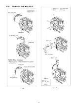
Page 22: ...nit 3 Front Case Unit Fig D5 1 Screw F 1 Screw G Fig D6 FP6003 Flex P6002 Connector P6004 Connector 1 Rib Front Case Unit 4 Camera Lens Unit Fig D7 FP6008 Flex Fig D8 P6001 Connector 1 Convex Camera Lens Unit 5 Main P C B SD Holder P C B Fig D9 5 Screws H P6003 Connector P6401 Connector FP6001 Flex FP6402 Flex 2 Ribs Fig D10 FP3201 Flex SD Holder P C B Main P C B Fig D11 NOTE When Installing 6 ESD...

Page 23: ...23 8 3 1 Removal of the Top Case Unit Fig D1 Fig D2 ...

Page 24: ...24 8 3 2 Removal of the Side Case L Unit Fig D3 Fig D4 8 3 3 Removal of the Front Case Unit Fig D5 ...

Page 25: ...25 Fig D6 8 3 4 Removal of the Camera Lens Unit Fig D7 Fig D8 8 3 5 Removal of the Main P C B and SD Holder P C B Fig D9 ...

Page 26: ...26 Fig D10 Fig D11 8 3 6 Removal of the ESD P C B Unit HDC TM80 only Fig D12 ...

Page 27: ...27 8 3 7 Removal of the Battery P C B Fig D13 Fig D14 ...

Page 28: ...PC Connection method of the main unit and an exclusive adjustment jig as follows 9 1 1 Adjustment Procedure Connect the main unit to PC with USB The adjustment instruction is available at Software download on the Support Information from NWBG VDBG AVC web site in TSN System Figure of connection Figure of image when adjustment Part Number of jig Only a necessary jig mentions it in setup of electric...

Page 29: ...29 Adjustment Items Adjustment item as follows The adjustment instruction is available at Software download on the Support Information from NWBG VDBG AVC web site in TSN System ...

Page 30: ...conds until the top screen of the Service Mode Menu being displayed 3 Touch the 1 of LCD 4 Touch the YES of LCD 5 After few seconds END is displayed or ESD NODATA as NG is displayed on LCD monitor Cutting of battery connection or AC power supply connection as a completion of the FACTORY SETTINGS After use at least once even if the physical format of the build in memory will be performed ESD NODATA...

Page 31: ...0 and file number is 0 4 Clear the mechanism lock information 5 Clear the service mode information contents 6 Close the lens cover 7 Initialize the VIERA Link Physical Address HDC TM80 If the Factory Settings is completed physical format of the build in memory is not performed execute physical format according to the following procedure The setting position of factory settings Name Setting positio...

Page 32: ... PC GK R Red Type only P PC PU GK Name of Signal OFTR FEP This signal is connected to the FEP schematic diagram Circuit name being connected 6 Use the parts number indicated on the Replacement Parts List 7 Indication on Schematic diagrams 5 The voltage being indicated here may be include observational error deviation due to internal resistance and or reactance of equipment Therefore handle the val...

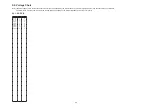
Page 33: ...tronic circuit tester high impedance with the chassis taken as standard Therefore there may exist some errors in the voltage values depending on the internal impedance of the DC circuit tester REF No PIN No POWER ON Q3901 E 3 3 Q3901 C 0 Q3901 B 3 3 QR6401 E 2 9 QR6401 C 0 4 QR6401 B 2 9 QR6402 E 2 9 QR6402 C 0 4 QR6402 B 2 9 ...

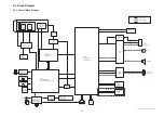
Page 34: ...ECTOR X301 OSC 60MHz ZOOM FOCUS MOTOR OIS Analog Analog Analog Analog IC6401 GYRO SENSOR CLK13M CLK12M IC3402 NAND FLASH ROM 512Mbit COLOR LCD PANEL IC3401 MPEG CODEC UNI PHIER XP2 IC3701 AVIO IC2006 SYSTEM CONTROL CAMERA MICROCOMPUTER IC1001 POWER CIRCUIT IC1501 1503 RTC CHARAGE POWER CONTROL IC2002 EEPROM NOTE VIDEO SIGNAL AUDIO SIGNAL CLK or CONTROL LINE IC301 CAMERA DSP BIANCA2 X2303 32 768kHz...

Page 35: ...19 21 23 25 27 29 31 33 FP6001 1 2 3 4 5 6 7 8 9 10 11 12 13 14 15 UARTO UARTI PW REG5V E CAM RST OCD SDA OCD SCL TRACECLK TRACESYNC EVRINJ TRACEPKT0 EVRINJ TRACEPKT1 TRACEPKT2 TRACEPKT3 TRACEPKT4 S AMMPTXD G XP2 RST 30 29 28 27 26 25 24 23 22 21 20 19 18 17 16 PS6001 FP6002 1 2 3 4 5 6 7 8 9 10 eSD1 DATA3 eSD1 DATA0 eSD1 DATA1 eSD1 DATA2 eSD1 CMD eSD1 D GND eSD1 CLK eSD1 DGND eSD1 VDD eSD1 VDD TR...

Page 36: ...T1 BUS24_SDDAT2 BUS24_SDDAT2 BUS24_SDDAT3 BUS24_SDDAT3 BUS24_SDDAT0 BUS24_SDDAT0 E_CARD_DET E_CARD_DET E_CARD_PRO E_CARD_PRO CLK49_SDCARD CLK49_SDCARD G_GYRO_REF G_GYRO_REF G_GYROY G_GYROY G_GYROP G_GYROP USB_IDDET_L USB_IDDET_L USB_D USB_D USB_D USB_D PW_VBUS PW_VBUS PW_VBUS_2 PW_VBUS_3 CARD_LED_B E_KEYIN1 E_KEYIN1 ZSW ZSW POWER_LED POWER_LED PHOTO_ZENOSI PHOTO_ZENOSI STANDBY_LEDB STANDBY_LEDB BU...

Page 37: ...6401 e QR6402 e QR6403 RL6401 RL6402 RX3901 RX3902 R3901 R3902 R3903 R3904 R3905 R3906 R3907 R3909 R6401 R6402 R6403 R6404 R6405 R6406 R6407 R6408 R6411 5 4 3 2 1 S6401 5 4 3 2 1 S6402 5 4 3 2 1 S6403 VA3901 VA6401 VA6403 VA6404 1 2 ZB6401 C3907 C6408 D6451 4 3 2 1 FL6401 4 3 13 11 10 12 8 7 6 5 4 3 2 1 9 14 HS3901 IP6401 3 2 1 JK6401 5 4 3 2 1 JK6402 LB6401 MK5 MK6 MK7 MK8 Q3901 R3908 R3910 R6409...

Page 38: ...his list 2 IMPORTANT SAFETY NOTICE Components identified with the mark have the special characteristics for safety When replacing any of these components use only the same type 3 Unless otherwise specified All resistors are in OHMS K 1 000 OHMS All capacitors are in MICRO FARADS uf P uuF 4 The marking RTL indicates the retention time is limited for this item After the discontinuation of this assem...

Page 39: ... 1U 1 C6407 F1G1C104A077 C CAPACITOR CH 16V 0 1U 1 C6408 ECJ1VB1A105K C CAPACITOR CH 10V 1U 1 C6412 F1H1E105A116 C CAPACITOR CH 25V 1U 1 D6451 B3AAB0000343 LED 1 E S D FP6402 K1MY10BA0370 CONNECTOR 10P 1 HS3901 K1NA09E00098 SD CARD SLOT 1 IC6401 EWTS9PSL11 IC 1 E S D IP6401 K5H4021A0011 IC PROTECTOR 1 JK6401 K2EBYB000003 JACK 1 JK6402 K2HZ105E0013 JK USB 1 LB6401 J0JJC0000015 FILTER 1 LB6402 J0JJC...

Page 40: ...NT CASE UNIT 1 S 6 VYK4S28 FRONT CASE UNIT 1 R 6 VYK4S50 FRONT CASE UNIT 1 T 6 VYK4S56 FRONT CASE UNIT 1 H 6 VYK4S84 FRONT CASE UNIT 1 C 7 VXW1217 CAMERA LENS UNIT 1 8 VWJ2260 FFC 1 HDC TM80 9 VYK4N24 SIDE CASE R UNIT 1 SD80EBK ECK EEK EFK EGK EPK GCK GKK GNK GTK PK PCK GAK 9 VYK4S35 SIDE CASE R UNIT 1 SD80EBS EES EGS EPS GCS GKS GNS PS PCS GAS 9 VYK4S41 SIDE CASE R UNIT 1 SD80EBR ECR EER EFR EGR ...

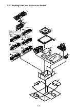
Page 41: ...RATING INSTRUCTIONS E 1 TM80PU 310 VQT3J18 OPERATING INSTRUCTIONS S 1 TM80PU 311 VPG2U91 PACKING CASE 1 SD80EBK ECK EEK EFK EGK EPK GCK GNK GTK GAK 311 VYQ6511 PACKING CASE UNIT 1 SD80EBS EES EGS EPS GCS GNS GAS 311 VYQ6512 PACKING CASE UNIT 1 SD80EBR ECR EER EFR EGR EPR GCR GNR GTR GAR 311 VYQ6513 PACKING CASE UNIT 1 T 311 VPG2U92 PACKING CASE 1 SD80EBH 311 VYQ6514 PACKING CASE UNIT 1 SD80GCC GAC...

Page 42: ...S7 Exploded View S7 1 Frame and Casing Section S 11 a 7 B8 a B7 B10 B9 4 5 B3 B4 B12 B11 B13 B15 B14 2 1 8 6 B2 B16 B17 3 B5 B6 B1 9 ...

Page 43: ...on S 12 305 309 310 301 311 312 322 313 307 321 306 303 302 319 HDC SD80P PC TM80P PC PU 317 HDC SD80GN 315 HDC SD80 EC EE EF EG EP GA GC 314 HDC SD80EB GA GC HDC TM80EB GA GC 316 HDC SD80GK TM80GK 318 HDC SD80GT HDC TM80 EC EE EF EG EP GA GC ...

Reviews: