


21
6 Service Mode
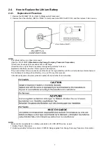
1.
Indication method of the service menu
Set the mode dial “Motion Picture Recording” mode.
2. Turn the power on, and then while keep pressing the "Zoom lever" to W side, "Intelligent auto/Manual" button and "Menu" but-
ton for more than 3 seconds until the top screen of the Service Mode Menu being displayed.
Service mode menu
NOTE:
Do not using service mode except above table of Service Menu.
3. End method of the top screen of the service menu
Push the menu button to end the service mode, and then POWER OFF.
Screen display
Contents
Function
1
Factory settings
Function to throw a product up in a factory shipment state
(When recorded data in HDD, “error display” is done)
2
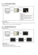
Drive information display
Fall detection frequency of HDD, Frequency that exceeds high-
est/lowest operation guarantee temperature and serial number
display
3
HDD self check execution
Function to check self as for the state of HDD
4
Lock search history indication
Display an error cord for three histories saved in EEPROM
5
Power ON self check result display
Power ON self check (function to diagnose correct function of
the device and interface between devices) result display
6
HDD hardware test
Function to confirm state of HDD hardware
Summary of Contents for HDC-HS700EB
Page 11: ...11 3 5 2 Precautions for installing HDD ...
Page 14: ...14 3 6 Formatting ...
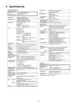
Page 15: ...15 4 Specifications ...
Page 16: ...16 ...
Page 17: ...17 ...
Page 30: ...30 Fig D2 8 3 2 Removal of the HDD Fig D3 ...
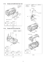
Page 32: ...32 8 3 5 Removal of the Front Unit Fig D7 8 3 6 Removal of the Side Case R Unit Fig D8 ...
Page 36: ...36 8 3 14 Removal of the Monitor P C B Unit Fig D19 Fig D20 ...
Page 38: ...38 Fig D24 8 3 17 Removal of the Front Case Fig D25 Fig D26 ...
Page 43: ...43 8 3 28 Removal of the IRIS Unit Fig D40 8 3 29 Removal of the Zoom Motor Fig D41 ...
Page 46: ...46 8 3 35 Removal of the Focus Guide Pole L and Focus Guide Pole S Fig D48 ...
Page 85: ...S7 3 EVF Section S 35 B23 59 B22 58 60 61 62 63 65 64 66 67 68 69 70 72 71 73 74 75 76 77 B24 ...
Page 86: ...S7 4 LCD Section S 36 27 28 29 26 30 32 23 31 25 22 B7 B8 24 ...


