background image

11

4 Specifications

Summary of Contents for HC-X900EB

Page 1: ... NO VM1202006CE B27 High Definition Video Camera Model No HC X900MP HC X900MPC HC X900MPU HC X900MEG HC X900MEP HC X900MEB HC X900MGC HC X900MEE HC X900MGN HC X900MGK HC X900EG HC X900EF HC X900EP HC X900EB HC X900GC HC X900EE HC X900GN HC X909EG Colour K Black Type S Silver Type only HC X909EG ...

Page 2: ...f Check Execution HC X900M only 19 6 2 Lock Search History Indication 19 6 3 Power ON Self Check Result Display 20 6 4 Forced full flash emission 21 6 5 Erasing the lock histories 21 6 6 Camera data indications while the video playback 22 7 Service Fixture Tools 23 7 1 When Replacing the Main P C B 23 7 2 Service Position 23 8 Disassembly and Assembly Instructions 25 8 1 Disassembly Flow Chart for...

Page 3: ...exposed to shock hazards 1 2 Leakage Current Cold Check 1 Unplug the AC cord and connect a jumper between the two prongs on the plug 2 Measure the resistance value with an ohmmeter between the jumpered AC plug and each exposed metal lic cabinet part on the equipment such as screwheads connectors control shafts etc When the exposed metal lic part has a return path to the chassis the reading should ...

Page 4: ...e capacitor also can be discharged according to the following procedures Discharging Procedure 1 Refer to the disassemble procedure and Remove the necessary parts unit 2 Put the insulation tube onto the lead part of Resistor ERG5SJ102 1kΩ 5W an equivalent type of resistor may be used 3 Put the resistor between both terminals of capacitor on FLASH P C B for approx 5 seconds 4 After discharging conf...

Page 5: ...ly a grounded tip soldering iron to solder or unsolder ES devices 4 Use only an antistatic solder removal device Some solder removal devices not classified as antistatic ESD protected can generate electrical charge sufficient to damage ES devices 5 Do not use freon propelled chemicals These can generate electrical charges sufficient to damage ES devices 6 Do not remove a replacement ES device from...

Page 6: ...must not be used until a replacement cover is obtained A replacement fuse cover can be purchased from your local Panasonic Dealer If the fitted moulded plug is unsuitable for the socket outlet in your home then the fuse should be removed and the plug cut off and disposed of safety There is a danger of severe electrical shock if the cut off plug is inserted into any 13 ampere socket If a new plug i...

Page 7: ... excessive heat or discharge It must therefore only be fitted in requirement designed specifically for its use Replacement batteries must be of same type and manufacture They must be fitted in the same manner and location as the original battery with the correct polarity contacts observed Do not attempt to re charge the old battery or re use it for any other purpose It should be disposed of in was...

Page 8: ... B using the lead free solder To put lead free solder it should be well molten and mixed with the original lead free solder Remove the remaining lead free solder on the P C B cleanly for soldering of the new IC Since the melting point of the lead free solder is higher than that of the normal lead solder it takes the longer time to melt the lead free solder Use the soldering iron more than 70W equi...

Page 9: ...ng label and caution label which are putted on the Unit NOTE After replacing the MAIN P C B be sure to achieve adjustment The adjustment instruction is available at software download on the Support Information from NWBG VDBG AVC web site in TSN system together with Maintenance software ...

Page 10: ...10 3 5 Formatting ...

Page 11: ...11 4 Specifications ...

Page 12: ...12 ...

Page 13: ...13 ...

Page 14: ...14 ...

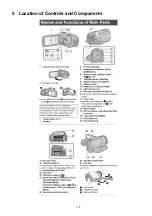
Page 15: ...15 5 Location of Controls and Components ...

Page 16: ...16 ...

Page 17: ...17 ...

Page 18: ...ct up in a factory shipment state 3 Built in memory self check exection HC X900M only Function to check self as for the state of Built in memory 4 Lock search history indication Display the camera system error cord for three histories saved in EEPROM 5 Power ON self check result dis play Power ON self check function to diagnose correct function of the device and interface between devices result di...

Page 19: ...dication contents Built in memory self check result display Display the Built in memory self check execution Displays other than OK are abnormalities of Built in memory Touch the BAK of LCD to end the service mode and then POWER OFF 6 2 Lock Search History Indication Touch the 4 of LCD select Lock search history indication Operation specifications ...

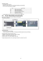
Page 20: ...k result display Function to diagnose correct function of the device and interface between devices result display Display the following communication test result CAM PWR Communication test between IC3401 to IC2304 CAM UNI IC3401 internal communication test Display other than OK are abnormalities of each lines Cutting of battery connection or AC power supply connection to end the service mode Error...

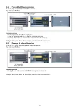
Page 21: ... To prevent electric shock we recommend enforcement before disassembling Cutting of battery connection or AC power supply connection to end the service mode 6 5 Erasing the lock histories Touch the 10 of LCD select erasing the lock histories execution Operation specifications Indication contents Erasing the error histories stored in EEPROM working time is not erased Cutting of battery connection o...

Page 22: ...the camera informations while playing back the recorded video Operation specifications Indication contents While playing back the recorded videos the camera informations Shutter speed Iris value White balance and focal length are superimposed on the LCD screen Press the power button and turn off ...

Page 23: ...or checking and replacing parts Use the following Extension cables for servicing Table S1 Extension Cable List No Parts No Connection Form 1 VFK1951 FP6004 MAIN MONITOR FPC 39PIN 0 3 FFC 2 RFKZ0564 FP851 BATTERY CATCHER EVF UNIT 23PIN 0 3 FFC 3 RFKZ0444 PP6005 MAIN PS6751 BATTERY CATCHER 50PIN 0 5 B to B 4 VFK1895 PP6006 MAIN PS7001 FLASH 40PIN 0 5 B to B 5 VFK1895 PP6002 MAIN PS3901 SD OP 40PIN 0...

Page 24: ... B Refer to How to Discharge the Capacitor on Flash P C B The capacitor voltage is not lowered soon even if the AC Cord is unplugged or the battery is removed 2 Be careful of the high voltage circuit on Flash P C B 3 DO NOT allow other parts to touch the high voltage circuit on Flash P C B ...

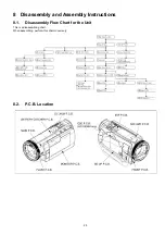
Page 25: ...25 8 Disassembly and Assembly Instructions 8 1 Disassembly Flow Chart for the Unit This is a disassembling chart When assembling perform this chart conversely 8 2 P C B Location ...

Page 26: ...n Damper 13 LCD Case T Unit Fig D16 2 Screws T Fig D17 2 Screws U Fig D18 6 Locking Tabs FP901 Flex FP902 Flex Side Case R Unit 14 Monitor P C B Fig D19 FP903 Flex FP904 Flex FP906 Flex 3 Ribs LCD Frame Fig D20 Reflection Sheet Light Guide Plate 15 LCD Panel Unit Fig D21 Diffusion Sheet Prism Sheet B Prism Sheet A Fig D22 LGP Holder TP Spacer LCD Case B Unit 16 Front P C B Fig D23 1 Screw V 1 Scre...

Page 27: ...unc FPC Camera Operation Angle 27 MIC AMP P C B Top Case Unit Fig D42 2 Locking Tabs FP4801 Flex FP4803 Flex MIC AMP FPC 28 Microphone Unit Fig D43 MIC Two Side Tape MIC Cushion A MIC Cushion B MIC Cushion C MIC Case 29 MOS Unit Fig D44 2 Screws j Optical Filter 30 Stepping Motor Fig D45 2 Screws k No Item Fig Removal ...

Page 28: ...28 8 3 1 Removal of the Side Case L Unit Fig D1 Fig D2 8 3 2 Removal of the SD OP P C B Fig D3 ...

Page 29: ...29 8 3 3 Removal of the Cover Board Unit Fig D4 8 3 4 Removal of the ESD P C B HC X900M only Fig D5 ...

Page 30: ...30 8 3 5 Removal of the Top OP Unit Fig D6 Fig D7 ...

Page 31: ...31 8 3 6 Removal of the Front Case Unit Fig D8 8 3 7 Removal of the Lens Unit Fig D9 8 3 8 Removal of the Side Case R Unit Fig D10 ...

Page 32: ...32 8 3 9 Removal of the Battery Catcher P C B Fig D11 8 3 10 Removal of the Main P C B Fig D12 ...

Page 33: ...33 Fig D13 8 3 11 Removal of the Flash P C B Fig D14 ...

Page 34: ...34 8 3 12 Removal of the Fan Motor Fig D15 8 3 13 Removal of the LCD Case T Unit Fig D16 Fig D17 ...

Page 35: ...35 Fig D18 8 3 14 Removal of the Monitor P C B Fig D19 Fig D20 8 3 15 Removal of the LCD Panel Unit Fig D21 ...

Page 36: ...36 Fig D22 8 3 16 Removal of the Front P C B Fig D23 8 3 17 Removal of the Barrier Motor Unit Fig D24 ...

Page 37: ...37 8 3 18 Removal of the Barrier Case Unit Fig D25 Fig D26 ...

Page 38: ...38 8 3 19 Removal of the MF Peace MF Ring MF Holl Delect FPC MF Front Case Fig D27 8 3 20 Removal of the EVF EXT P C B Fig D28 Fig D29 ...

Page 39: ...39 Fig D30 Fig D31 Fig D32 ...

Page 40: ...40 8 3 21 Removal of the EVF Lens Holder Unit Fig D33 Fig D34 ...

Page 41: ...41 8 3 22 Removal of the Top Frame Fig D35 8 3 23 Removal of the Zoom Operation Unit Fig D36 Fig D37 ...

Page 42: ...42 8 3 24 Removal of the S S Case Unit Fig D38 8 3 25 Removal of the DC Jack P C B Fig D39 Fig D40 ...

Page 43: ...43 8 3 26 Removal of the Camera Operation Case Fig D41 8 3 27 Removal of the MIC AMP P C B Top Case Unit Fig D42 8 3 28 Removal of the Microphone Unit Fig D43 ...

Page 44: ...44 8 3 29 Removal of the MOS Unit Fig D44 8 3 30 Removal of the Stepping Motor Fig D45 ...

Page 45: ...sary for electric adjustment A USB driver for service is necessary to communication with PC Connection method of the main unit and an exclusive adjustment jig as follows 9 1 1 Adjustment Procedure Connect the main unit to PC with USB The adjustment instruction is available at Software download on the Support Information from NWBG VDBG AVC web site in TSN System Figure of connection Figure of image...

Page 46: ...instruction is available at Software download on the Support Information from NWBG VDBG AVC web site in TSN System No Part Name Part Number Remarks 1 PC 2 AC Adaptor 3 USB Cable 5 Adjustment Software Tatsujin 6 C4 Filter VFK1164LBB4 The same as C12 Filter VFK1164LBB12 7 C8 Filter VFK1164LBB8 8 ND Filter 0 1 VFK1164ND01 9 ND Filter 0 6 VFK1164ND06 ...

Page 47: ...l the top screen of the Service Mode Menu being displayed 3 Touch the 1 of LCD 4 Touch the YES of LCD 5 After few seconds END is displayed or ESD NODATA as NG is displayed on LCD monitor Cutting of battery connection or AC power supply connection as a completion of the FACTORY SETTINGS After recording at least once even if the physical format of the build in memory will be performed ESD NODATA as ...

Page 48: ...on 5 Clear the service mode information contents 6 Clear the setting date 7 Close the lens cover 8 Initialize the VIERA Link Physical Address 9 Rewriting lock setup of destination information HC X900M If the Factory Settings is completed physical format of the build in memory is not performed execute physical format according to the following procedure The setting position of factory settings Name...

Page 49: ...OR OIS Analog Analog Analog Analog Analog IC6301 GYRO SENSOR CLK74 IC3402 DDR SDRAM IC901 SUB LVDS COLOR EVF PANEL IC3401 IC3701 AVIO IC1001 1501 BATTERY CHARGER POWER CIRCUIT IC2304 RTC NOTE VIDEO SIGNAL AUDIO SIGNAL CLK or CONTROL LINE IC301 CAMERA DSP SIRIUS X2301 32 768kHz EXTERNAL MIC Q4901 4904 4907 4908 MIC AMP Analog Analog TOUCH PANEL IC2701 3D ADAPTOR DET INTERNAL MEMORY IC6351 ROLL GYRO...

Page 50: ... E PHOTO SW To IC301 A17 B16 A28 QR3405 QR3409 S6601 CAMERA FUNCTION S6003 60P SW S NOTICE SCK S NOTICE CS S NOTICE DO S NOTICE DI U30 W29 F31 V31 R30 14 SW1 S6002 POWER SW FAN FULL ON FAN OFF H FAN FG B23 A14 G19 Q1452 4 5 3 1 2 QR1452 PW 5V PW FAN5V Q1451 CH331 FAN UNIT QR1453 AD TPY RIGHT AD TPX BOT B29 A29 AD TPY LEFT AD TPX TOP B28 C28 SEL1 ON LOW F18 SEL2 ON LOW G17 SEL1 ON HI AL29 QR3411 QR...

Page 51: ... IC3403 NAND FLASH ROM 512Mbit IC3402 DDR SDRAM 33 36 29 18 13 11 19 8 21 CTL SIG CKB DM3 DM2 DM1 DM0 BA0 A BA1 M2 L3 P2 W3 R3 T4 V2 WE CAS RAS CS CKE CK N3 R4 M3 N4 P1 N2 CTL SIG ADDRESS S DO L CD S CS LCD S CLK LCD D0P LCD D0N LCD D1P LCD D1N LCD CLKP LCD CLKN LCD AL5 AK5 AL7 AK7 AL6 AK6 LCD LVDS 0P LCD LVDS 0N LCD LVDS 1P LCD LVDS 1N LCD LVDS CLKP LCD LVDS CLKN 85 72 69 62 59 52 24 17 14 7 To I...

Page 52: ... RL3701 RL3709 RL3708 HC X900 HC X909 VIDEO AUDIO SIGNAL PROCESS 2 CIRCUIT BLOCK DIAGRAM G EXTMIC L G MIC OUT R G MIC OUT L G MIC OUT B G MIC OUT C G MIC OUT F 3D SW LCD PANEL LVOUT R0 7 LVOUT B0 7 LVOUT G0 7 H2 J2 DRV2 DRV1 G5 H3 R7 R0 C3 D3 R7 R0 H9 J6 G7 G0 A5 B3 G7 G0 E8 G7 E9 D9 D8 D7 B7 XHD OUT DE OUT XVD OUT CLK OUT C9 B9 A8 CLKIN XHDIN XVDIN B0 B8 C6 B7 B0 IC902 LCD DRIVER F6 H5 R7 R0 A7 E...

Page 53: ... P BCK M To IC3401 MPEG CODEC CS SENS G CS SENS B TG GLVDL HDL MOS RST LVBACH3DOP LVBACH4DOM LVBACH4DOP A5 XCLK IN AG23 MOS IMAGE SENSOR x 3 CH307 CH306 32 33 29 28 27 26 35 34 38 37 22 PS6011 CH308 PS6011 PS6011 PS6011 59 58 2 3 4 5 56 57 53 54 7 9 11 13 12 10 24 CH305 CH304 CH303 CH302 5 1 4 3 2 IC303 GATE IC PW REG1 8V 5 1 4 3 2 IC304 GATE IC PW REG1 8V X301 60MHz 5 1 4 2 IC302 REGULATOR PW MOS...

Page 54: ...AK27 CH711 CH712 CH713 QR775 MF RING2 MF RING1 D31 D30 IC301 CAMERA DSP S NSCS LEN S DACLD LEN E LENS RST L LEDCONT LEN B21 B24 D23 S LENDATL2P S SCK LEN A22 A23 C23 S LENDATP2L A24 CH718 CH722 CH723 CH721 CH719 CH720 4 5 3 1 IC708 LOGIC IC D Q VCC LE 4 2 3 5 IC707 INVERTER INA OUTY PW REG3V PW REG3V VCC 4 5 3 1 IC6352 GYRO AMP VDD OUT IN IN PW GYRO 3V 1 4 3 IC6351 ROLL GYRO SENSOR VRFF OUT SENS S...

Page 55: ... IC3401 DIGITAL SIGNAL PROCESSOR IC1503 LOGIC IC IC2304 RTC 12 CONP1 9 WKUP 10 CONP2 SW NOREG N31 N30 E30 13 VDD B25 1 3 2 INH VEE 4 G COM 8 6 7 CH0 CH1 5 CTRL VCC QR1505 QR1506 QR1502 QR1504 B3901 LI BATT Q1502 1 2 3 4 5 6 8 7 IC1502 COMPARATOR 8 6 7 B OUT B IN 5 B IN V 1 3 2 A IN A IN 4 GND A OUT S SDA AV CH S CLK AV CH CHG EN IP6752 IP6801 QR1503 4 QR1101 CL1105 5 1 VOUT VSS CNT 4 NC IC2303 REG...

Page 56: ...㪈㪌 㪛㪘㪫㪘㪇 㪈㪋 㪛㪘㪫㪘㪈 㪈㪊 㪛㪘㪫㪘㪉 㪈㪉 㪛㪘㪫㪘㪊 㪈㪈 㪥㪚 㪈㪇 㪛㪘㪫㪘㪋 㪐 㪛㪘㪫㪘㪌 㪏 㪛㪘㪫㪘㪍 㪎 㪛㪘㪫㪘㪎 㪍 㪪㪛㪘㪫 㪌 㪪㪦㪬㪫 㪋 㪪㪚㪣㪢 㪊 㪪㪜㪥 㪉 㪞㪥㪛 㪈 㪭㪚㪚㪌㪭 㪉㪉 㪭㪛㪛㪉㪩㪌 㪉㪇 㪚㪣㪦㪚㪢 㪈㪏 㪛㪘㪫㪘㪇 㪈㪍 㪛㪘㪫㪘㪉 㪈㪋 㪛㪘㪫㪘㪋 㪈㪉 㪛㪘㪫㪘㪍 㪈㪇 㪛㪶㪞㪥㪛 㪏 㪛㪶㪞㪥㪛 㪍 㪛㪶㪞㪥㪛 㪋 㪪㪜㪥 㪉 㪭㪚㪚㪌㪭 㪉㪊 㪜㪭㪝㪶㪪㪣㪠㪛㪜㪶㪪㪮 㪉㪈 㪛㪶㪞㪥㪛 㪈㪐 㪛㪶㪞㪥㪛 㪈㪎 㪛㪘㪫㪘㪈 㪈㪌 㪛㪘㪫㪘㪊 㪈㪊 㪛㪘㪫㪘㪌 㪈㪈 㪛㪘㪫㪘㪎 㪐 㪛㪶㪞㪥㪛 㪎 㪛㪶㪞㪥㪛 㪌 㪪㪛㪘㪫 㪊 㪪㪚㪣㪢 㪈 㪭㪚㪚㪌㪭 㪉㪉 㪜㪭㪝㪶㪪㪣㪠㪛㪜㪶㪪㪮 㪉㪇 㪛㪶㪞㪥㪛 㪈㪏 㪛㪶㪞㪥㪛 㪈㪍 㪛㪘㪫㪘㪈 㪈㪋 㪛㪘㪫㪘㪊 㪈㪉 㪛㪘㪫㪘㪌 㪈㪇 㪛㪘㪫㪘㪎 㪏 㪛㪶㪞㪥㪛 㪍 㪛㪶...

Page 57: ...Model No HC X900MP MPC MPU MEG MEP MEB MGC MEE MGN MGK HC X900EG EF EP EB GC EE GN HC X909EG Schematic Diagram Note 6 ...

Page 58: ...Model No HC X900MP MPC MPU MEG MEP MEB MGC MEE MGN MGK HC X900EG EF EP EB GC EE GN HC X909EG Parts List Note 6 ...

Page 59: ...Model No HC X900MP MPC MPU MEG MEP MEB MGC MEE MGN MGK HC X900EG EF EP EB GC EE GN HC X909EG Main connection Main P C B 6 ...

Page 60: ...Model No HC X900MP MPC MPU MEG MEP MEB MGC MEE MGN MGK HC X900EG EF EP EB GC EE GN HC X909EG Video Main P C B 6 ...

Page 61: ...Model No HC X900MP MPC MPU MEG MEP MEB MGC MEE MGN MGK HC X900EG EF EP EB GC EE GN HC X909EG Process Main P C B 6 ...

Page 62: ...Model No HC X900MP MPC MPU MEG MEP MEB MGC MEE MGN MGK HC X900EG EF EP EB GC EE GN HC X909EG Lens Drive Main P C B 6 ...

Page 63: ...Model No HC X900MP MPC MPU MEG MEP MEB MGC MEE MGN MGK HC X900EG EF EP EB GC EE GN HC X909EG AVIO Main P C B 6 ...

Page 64: ...Model No HC X900MP MPC MPU MEG MEP MEB MGC MEE MGN MGK HC X900EG EF EP EB GC EE GN HC X909EG Charge RTC Main P C B 6 ...

Page 65: ...Model No HC X900MP MPC MPU MEG MEP MEB MGC MEE MGN MGK HC X900EG EF EP EB GC EE GN HC X909EG Power Main P C B 6 ...

Page 66: ...Model No HC X900MP MPC MPU MEG MEP MEB MGC MEE MGN MGK HC X900EG EF EP EB GC EE GN HC X909EG SD OP SD OP P C B 6 ...

Page 67: ...Model No HC X900MP MPC MPU MEG MEP MEB MGC MEE MGN MGK HC X900EG EF EP EB GC EE GN HC X909EG Battery Catcher Battery Catcher P C B 6 ...

Page 68: ...Model No HC X900MP MPC MPU MEG MEP MEB MGC MEE MGN MGK HC X900EG EF EP EB GC EE GN HC X909EG Front Front P C B 6 ...

Page 69: ...Model No HC X900MP MPC MPU MEG MEP MEB MGC MEE MGN MGK HC X900EG EF EP EB GC EE GN HC X909EG Mic Amp Mic Amp P C B 6 ...

Page 70: ...Model No HC X900MP MPC MPU MEG MEP MEB MGC MEE MGN MGK HC X900EG EF EP EB GC EE GN HC X909EG Flash Flash P C B 6 ...

Page 71: ...Model No HC X900MP MPC MPU MEG MEP MEB MGC MEE MGN MGK HC X900EG EF EP EB GC EE GN HC X909EG EVF EXT EVF EXT P C B 6 ...

Page 72: ...Model No HC X900MP MPC MPU MEG MEP MEB MGC MEE MGN MGK HC X900EG EF EP EB GC EE GN HC X909EG DC Jack DC Jack P C B 6 ...

Page 73: ...Model No HC X900MP MPC MPU MEG MEP MEB MGC MEE MGN MGK HC X900EG EF EP EB GC EE GN HC X909EG Monitor Monitor P C B 6 ...

Page 74: ...Model No HC X900MP MPC MPU MEG MEP MEB MGC MEE MGN MGK HC X900EG EF EP EB GC EE GN HC X909EG Cam Func Cam Func FPC 6 ...

Page 75: ...Model No HC X900MP MPC MPU MEG MEP MEB MGC MEE MGN MGK HC X900EG EF EP EB GC EE GN HC X909EG MF Holl Detect MF Holl Detect FPC 6 ...

Page 76: ...Model No HC X900MP MPC MPU MEG MEP MEB MGC MEE MGN MGK HC X900EG EF EP EB GC EE GN HC X909EG Main P C B Component Side 6 ...

Page 77: ...Model No HC X900MP MPC MPU MEG MEP MEB MGC MEE MGN MGK HC X900EG EF EP EB GC EE GN HC X909EG Main P C B Foil Side 6 ...

Page 78: ...Model No HC X900MP MPC MPU MEG MEP MEB MGC MEE MGN MGK HC X900EG EF EP EB GC EE GN HC X909EG SD OP P C B Component Side 6 ...

Page 79: ...Model No HC X900MP MPC MPU MEG MEP MEB MGC MEE MGN MGK HC X900EG EF EP EB GC EE GN HC X909EG SD OP P C B Foil Side 6 ...

Page 80: ...Model No HC X900MP MPC MPU MEG MEP MEB MGC MEE MGN MGK HC X900EG EF EP EB GC EE GN HC X909EG Battery Catcher P C B Component Side 6 ...

Page 81: ...Model No HC X900MP MPC MPU MEG MEP MEB MGC MEE MGN MGK HC X900EG EF EP EB GC EE GN HC X909EG Battery Catcher P C B Foil Side 6 ...

Page 82: ...Model No HC X900MP MPC MPU MEG MEP MEB MGC MEE MGN MGK HC X900EG EF EP EB GC EE GN HC X909EG Front P C B Component Side 6 ...

Page 83: ...Model No HC X900MP MPC MPU MEG MEP MEB MGC MEE MGN MGK HC X900EG EF EP EB GC EE GN HC X909EG Front P C B Foil Side 6 ...

Page 84: ...Model No HC X900MP MPC MPU MEG MEP MEB MGC MEE MGN MGK HC X900EG EF EP EB GC EE GN HC X909EG Mic Amp P C B Component Side 6 ...

Page 85: ...Model No HC X900MP MPC MPU MEG MEP MEB MGC MEE MGN MGK HC X900EG EF EP EB GC EE GN HC X909EG Mic Amp P C B Foil Side 6 ...

Page 86: ...Model No HC X900MP MPC MPU MEG MEP MEB MGC MEE MGN MGK HC X900EG EF EP EB GC EE GN HC X909EG Flash P C B Component Side 6 ...

Page 87: ...Model No HC X900MP MPC MPU MEG MEP MEB MGC MEE MGN MGK HC X900EG EF EP EB GC EE GN HC X909EG Flash P C B Foil Side 6 ...

Page 88: ...Model No HC X900MP MPC MPU MEG MEP MEB MGC MEE MGN MGK HC X900EG EF EP EB GC EE GN HC X909EG EVF EXT P C B Component Side 6 ...

Page 89: ...Model No HC X900MP MPC MPU MEG MEP MEB MGC MEE MGN MGK HC X900EG EF EP EB GC EE GN HC X909EG EVF EXT P C B Foil Side 6 ...

Page 90: ...Model No HC X900MP MPC MPU MEG MEP MEB MGC MEE MGN MGK HC X900EG EF EP EB GC EE GN HC X909EG DC Jack P C B Component Side 6 ...

Page 91: ...Model No HC X900MP MPC MPU MEG MEP MEB MGC MEE MGN MGK HC X900EG EF EP EB GC EE GN HC X909EG DC Jack P C B Foil Side 6 ...

Page 92: ...Model No HC X900MP MPC MPU MEG MEP MEB MGC MEE MGN MGK HC X900EG EF EP EB GC EE GN HC X909EG Monitor P C B Component Side 6 ...

Page 93: ...Model No HC X900MP MPC MPU MEG MEP MEB MGC MEE MGN MGK HC X900EG EF EP EB GC EE GN HC X909EG Monitor P C B Foil Side 6 ...

Page 94: ...Model No HC X900MP MPC MPU MEG MEP MEB MGC MEE MGN MGK HC X900EG EF EP EB GC EE GN HC X909EG Cam Func P C B Component Side 6 ...

Page 95: ...Model No HC X900MP MPC MPU MEG MEP MEB MGC MEE MGN MGK HC X900EG EF EP EB GC EE GN HC X909EG Cam Func P C B Foil Side 6 ...

Page 96: ...Model No HC X900MP MPC MPU MEG MEP MEB MGC MEE MGN MGK HC X900EG EF EP EB GC EE GN HC X909EG MF Holl Detect P C B Component Side 6 ...

Page 97: ...Model No HC X900MP MPC MPU MEG MEP MEB MGC MEE MGN MGK HC X900EG EF EP EB GC EE GN HC X909EG MF Holl Detect P C B Foil Side 6 ...

Page 98: ...F1G0J1050007 C CAPACITOR CH 6 3V 1U 1 C338 F1L1A103A016 C CAPACITOR CH 10V 0 01U 1 C701 F1G0J1050007 C CAPACITOR CH 6 3V 1U 1 C702 F1G0J1050007 C CAPACITOR CH 6 3V 1U 1 C703 F1J0J106A049 C CAPACITOR CH 6 3V 10U 1 C704 F1G0J1050007 C CAPACITOR CH 6 3V 1U 1 C705 F1G0J1050007 C CAPACITOR CH 6 3V 1U 1 C708 F1J0J106A049 C CAPACITOR CH 6 3V 10U 1 C709 F1J0J106A049 C CAPACITOR CH 6 3V 10U 1 C713 F1G1H101...

Page 99: ...R CH 50V 22P 1 C916 F1G1H220A644 C CAPACITOR CH 50V 22P 1 C917 F1G1H220A644 C CAPACITOR CH 50V 22P 1 C918 F1G1H220A644 C CAPACITOR CH 50V 22P 1 C919 F1G1H220A644 C CAPACITOR CH 50V 22P 1 C920 F1G1H220A644 C CAPACITOR CH 50V 22P 1 C921 F1G1H220A644 C CAPACITOR CH 50V 22P 1 C922 F1G1H220A644 C CAPACITOR CH 50V 22P 1 C923 F1G1H220A644 C CAPACITOR CH 50V 22P 1 C924 F1G1H220A644 C CAPACITOR CH 50V 22P ...

Page 100: ...CITOR CH 10V 0 047U 1 C1103 F1G1C104A077 C CAPACITOR CH 16V 0 1U 1 C1104 F1G1C104A077 C CAPACITOR CH 16V 0 1U 1 C1105 F1G0J1050007 C CAPACITOR CH 6 3V 1U 1 C1106 F1J1A106A043 C CAPACITOR CH 10V 10U 1 C1107 F1G0J1050007 C CAPACITOR CH 6 3V 1U 1 C1109 F1G0J1050007 C CAPACITOR CH 6 3V 1U 1 C1112 F1G1H472A571 C CAPACITOR CH 50V 4700P 1 C1122 F1G1H472A571 C CAPACITOR CH 50V 4700P 1 C1132 F1G1H332A640 C...

Page 101: ...409 F1L0J1040001 C CAPACITOR CH 6 3V 0 1U 1 C3410 F1L0J1040001 C CAPACITOR CH 6 3V 0 1U 1 C3411 F1L0J1040001 C CAPACITOR CH 6 3V 0 1U 1 C3412 F1G1C104A077 C CAPACITOR CH 16V 0 1U 1 C3413 F1G1C104A077 C CAPACITOR CH 16V 0 1U 1 C3414 F1G1C104A077 C CAPACITOR CH 16V 0 1U 1 C3415 F1G1C104A077 C CAPACITOR CH 16V 0 1U 1 C3416 F1G1C104A077 C CAPACITOR CH 16V 0 1U 1 C3417 F1G1C104A077 C CAPACITOR CH 16V 0...

Page 102: ... C3704 F1G1C104A077 C CAPACITOR CH 16V 0 1U 1 C3705 F1G1C104A077 C CAPACITOR CH 16V 0 1U 1 C3706 F1G1C104A077 C CAPACITOR CH 16V 0 1U 1 C3707 F1G0J1050007 C CAPACITOR CH 6 3V 1U 1 C3708 F1H0J4750004 C CAPACITOR CH 6 3V 4 7U 1 C3709 F1G0J1050007 C CAPACITOR CH 6 3V 1U 1 C3710 F1J1A106A043 C CAPACITOR CH 10V 10U 1 C3711 F1L1A103A016 C CAPACITOR CH 10V 0 01U 1 C3712 F1J1A106A043 C CAPACITOR CH 10V 10...

Page 103: ... 3V 0 1U 1 C6009 F1L0J1040001 C CAPACITOR CH 6 3V 0 1U 1 C6024 F1L0J1040001 C CAPACITOR CH 6 3V 0 1U 1 C6025 F1L0J1040001 C CAPACITOR CH 6 3V 0 1U 1 C6098 F1L0J1040001 C CAPACITOR CH 6 3V 0 1U 1 C6099 F1L0J1040001 C CAPACITOR CH 6 3V 0 1U 1 C6112 F1L0J1040001 C CAPACITOR CH 6 3V 0 1U 1 C6301 F1G1C104A077 C CAPACITOR CH 16V 0 1U 1 C6302 F1G1C104A077 C CAPACITOR CH 16V 0 1U 1 C6304 F1J1A106A043 C CA...

Page 104: ...1000208 EARTH TERMINAL 1 FL6001 J0ZZB0000122 FILTER 1 FL6002 J0ZZB0000122 FILTER 1 FL6004 F1H0J105A037 C CAPACITOR CH 6 3V 1U 1 FP801 K1MY23BA0235 CONNECTOR 23P 1 FP802 K1MY22BA0370 CONNECTOR 22P 1 FP851 K1MN23AA0035 CONNECTOR 23P 1 FP901 K1MY16BA0159 CONNECTOR 16P 1 FP902 K1MY12BA0159 CONNECTOR 12P 1 FP903 K1MY04BA0370 CONNECTOR 4P 1 FP904 K1MN57BA0047 CONNECTOR 57P 1 FP905 K1MN04BA0262 CONNECTOR...

Page 105: ...S9PSL1A IC 1 E S D IC6351 L2ES00000039 IC 1 E S D IC6352 C0ABGA000035 IC 1 E S D IC7001 C0ZBZ0001992 IC 1 E S D IC7101 C0DBAYY01077 IC 1 E S D IC7111 C0CBCCC00157 IC 1 E S D IP6752 K5H402YA0080 IC PROTECTOR 1 IP6801 K5H402YA0080 IC PROTECTOR 1 IR6401 B3RBB0000013 REMOTE SENSOR 1 JK3301 K2HZ112E0002 JACK AV MULTI 1 JK4901 K2HC104B0047 JACK EXT MIC 1 JK4902 K2HC106E0007 JACK HEADPHNE 1 JK6751 K4ZZ04...

Page 106: ...5 FILTER 1 LB6802 J0JJC0000015 FILTER 1 P6001 K1KA02AA0051 CONNECTOR 2P 1 P6302 K1KA03BA0014 CONNECTOR 3P 1 P6752 K1KY05BA0314 CONNECTOR 5P 1 P6801 K1KY05BA0314 CONNECTOR 5P 1 P7001 K1KA02B00292 CONNECTOR 2P 1 P7002 K1KA02BA0022 CONNECTOR 2P 1 PP6002 K1KA40BA0052 CONNECTOR 40P 1 PP6005 K1KY50BA0082 CONNECTOR 50P 1 PP6006 K1KY40AA0384 CONNECTOR 40P 1 PS3901 K1KB40AA0094 CONNECTOR 40P 1 PS6011 K1KY6...

Page 107: ... E S D QR2301 DRA3144E0L TRANSISTOR RESISTOR 1 E S D QR3401 DRC3144W0L TRANSISTOR RESISTOR 1 E S D QR3402 DRA3144E0L TRANSISTOR RESISTOR 1 E S D QR3405 DRA3114Y0L TRANSISTOR RESISTOR 1 E S D QR3406 DRA3114Y0L TRANSISTOR RESISTOR 1 E S D QR3408 DRA3114Y0L TRANSISTOR RESISTOR 1 E S D QR3409 DRA3114T0L TRANSISTOR RESISTOR 1 E S D QR3410 DRC3143T0L TRANSISTOR RESISTOR 1 E S D QR3411 DRA3143T0L TRANSIS...

Page 108: ...R1002 D1JB2R70A023 FUSING RESISTOR 2 7 1 R1003 D1JBR045A055 FUSING RESISTOR 0 045 1 R1006 ERJ2GEJ104 M RESISTOR CH 1 10W 100K 1 R1101 ERJ2RHD473 M RESISTOR CH 1 16W 47K 1 R1102 ERJ1GE0R00C M RESISTOR CH 1 20W 0 1 R1106 ERJ1GE0R00C M RESISTOR CH 1 20W 0 1 R1107 ERJ1GEJ103 M RESISTOR CH 1 20W 10K 1 R1109 ERJ1GE0R00C M RESISTOR CH 1 20W 0 1 R1110 ERJ2GEJ223 M RESISTOR CH 1 16W 22K 1 R1111 ERJ2GEJ202 ...

Page 109: ...1 16W 220K 1 R1520 ERJ2RHD104 M RESISTOR CH 1 16W 100K 1 R1601 D1JBR045A055 FUSING RESISTOR 0 045 1 R1602 ERJ2RHD203 M RESISTOR CH 1 16W 20K 1 R1604 ERJ3GEYJ4R7 M RESISTOR CH 1 10W 4 7 1 R1605 ERJ8GEYJ330 M RESISTOR CH 1 8W 33 1 R2301 ERJ2GEJ334 M RESISTOR CH 1 16W 330K 1 R2302 ERJ2GEJ102Y M RESISTOR CH 1 10W 1K 1 R2305 ERJ2GEJ473Y M RESISTOR CH 1 10W 47K 1 R2307 ERJ2GEJ105 M RESISTOR CH 1 10W 1M ...

Page 110: ... 10W 10K 1 R3487 ERJ2GEJ101 M RESISTOR CH 1 10W 100 1 R3492 ERJ2GEJ103 M RESISTOR CH 1 10W 10K 1 R3493 ERJ2GEJ103 M RESISTOR CH 1 10W 10K 1 R3505 ERJ1GEJ473 M RESISTOR CH 1 20W 47K 1 R3510 ERJ2GEJ472 M RESISTOR CH 1 10W 4 7K 1 R3511 ERJ2GEJ472 M RESISTOR CH 1 10W 4 7K 1 R3514 ERJ2GEJ103 M RESISTOR CH 1 10W 10K 1 R3703 ERJ1GEJ102 M RESISTOR CH 1 20W 1K 1 R3712 ERJ1GEJ102 M RESISTOR CH 1 20W 1K 1 R3...

Page 111: ...R CH 1 16W 2 2 1 R6004 ERJ1GEJ101 M RESISTOR CH 1 20W 100 1 R6019 ERJ1GEJ392 M RESISTOR CH 1 20W 3 9K 1 R6021 ERJ1GEJ101 M RESISTOR CH 1 20W 100 1 R6086 D0YAR0000007 M RESISTOR CH 1 10W 0 1 R6087 D0YAR0000007 M RESISTOR CH 1 10W 0 1 R6088 ERJ2GEJ102Y M RESISTOR CH 1 10W 1K 1 R6089 ERJ2GEJ102Y M RESISTOR CH 1 10W 1K 1 R6352 ERJ2GEJ223 M RESISTOR CH 1 16W 22K 1 R6353 ERJ2GEJ394 M RESISTOR CH 1 16W 3...

Page 112: ...4 RESISTOR NETWORKS 1 RX3401 D1H82704A024 RESISTOR NETWORKS 1 RX3402 D1H85604A024 RESISTOR NETWORKS 1 HC X900M RX3408 EXB28V103JX RESISTOR NETWORKS 1 RX3901 D1H85604A024 RESISTOR NETWORKS 1 RX3902 EXB28V103JX RESISTOR NETWORKS 1 RX3951 D1H86834A024 RESISTOR 1 HC X900M S801 ESE18L62BXFD SWITCH 1 S6002 K0H1BA000580 SWITCH 1 S6003 K0H1BA000580 SWITCH 1 S6601 K0F111A00589 SWITCH 1 S6801 K0F111A00471 S...

Page 113: ...Model No HC X900MP MPC MPU MEG MEP MEB MGC MEE MGN MGK HC X900EG EF EP EB GC EE GN HC X909EG Frame and Casing Section 1 6 ...

Page 114: ...Model No HC X900MP MPC MPU MEG MEP MEB MGC MEE MGN MGK HC X900EG EF EP EB GC EE GN HC X909EG Frame and Casing Section 2 6 ...

Page 115: ...Model No HC X900MP MPC MPU MEG MEP MEB MGC MEE MGN MGK HC X900EG EF EP EB GC EE GN HC X909EG EVF Section 6 ...

Page 116: ...Model No HC X900MP MPC MPU MEG MEP MEB MGC MEE MGN MGK HC X900EG EF EP EB GC EE GN HC X909EG LCD Section 6 ...

Page 117: ...Model No HC X900MP MPC MPU MEG MEP MEB MGC MEE MGN MGK HC X900EG EF EP EB GC EE GN HC X909EG Packing Parts and Accessories Section 6 ...

Page 118: ... P C B UNIT 1 RTL 23 VEE1K04 DC BATTERY WIRE 1 24 VYK5J33 S S CASE UNIT 1 25 VGQ0M76 PHOTO CUSHION 1 26 VMP0A56 TOP FRAME 1 27 VGU0F89 CAMERA OPERATION BUTTON 1 28 VGQ0K85 CAMERA OPERATION CASE 1 29 VMP0A57 CAMERA OPERATION ANGLE 1 30 VGQ0M74 CAMERA DAMPER SHEET 1 31 VEP20D76A CAM FUNC FPC UNIT 1 RTL 32 VEP04982A MIC AMP P C B UNIT 1 RTL E S D 33 VWJ2278 MIC AMP FPC 1 34 VGQ1A81 EVF SLIDE CASE 1 3...

Page 119: ...ENSOR WINDOW 1 79 VYK5D79 COVER BOARD UNIT 1 80 VGQ1D19 HEAT RADIATION SHEET A 1 201 VXQ2122 MOS UNIT 1 202 VXW1301 LENS UNIT 1 202 1 L6HAYYYB0006 STEPPING MOTOR 1 203 VDL1900 OPTICAL FILTER 1 B32 VHD1919 SCREW 1 301 BATTERY PACK 1 900MP MPC 301 BATTERY PACK 1 900MPU MEG MEP MEB MGC MEE MGN 900EG E F EP EB GC EE GN 909EG 301 BATTERY PACK 1 900MGK 302 K1HY12YY0012 AV MULTI CABLE 1 303 K2KYYYY00201 ...

Page 120: ...G CASE 1 900MP K MPC K 318 VYQ7770 PACKING CASE U 1 900MPU K 318 VPG3F91 PACKING CASE 1 900MEG K MEP K MEB K MGC K MEE K MGN K 318 VYQ7769 PACKING CASE U 1 900MGK K 318 VPG3F92 PACKING CASE 1 900EG K EF K EP K EB K GC K EE K GN K 318 VPG3F93 PACKING CASE 1 909EG K 318 VYQ7768 PACKING CASE U 1 909EG S 319 VPN7380 PAD 1 320 VPF1448 PROTECT BAG 1 B51 VHD1919 SCREW 1 B63 VHD1919 SCREW 1 B64 VHD1919 SC...

Page 121: ...6 B4FJK SCREW 1 B44 XQN16 B4FJK SCREW 1 B45 XQN16 B4FJK SCREW 1 B46 XQN16 B4FJK SCREW 1 B47 XQN16 B4FJK SCREW 1 B48 XQN16 B4FJK SCREW 1 B49 XQN16 B4FJK SCREW 1 B50 XQN16 B4FJK SCREW 1 B52 XQN16 B4FJK SCREW 1 B53 XQN16 B4FJK SCREW 1 B54 XQN16 B4FJK SCREW 1 B55 XQN16 BJ4FJK SCREW 1 B56 XQN16 BJ4FJK SCREW 1 B57 VHD2189 SCREW 1 B58 VHD1907 SCREW 1 B59 VHD1907 SCREW 1 B60 VHD1907 SCREW 1 B61 VHD1907 SC...

Reviews: