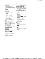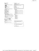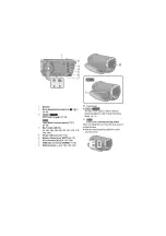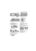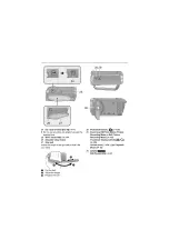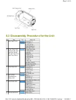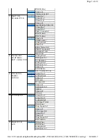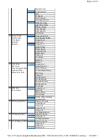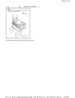
8.3 Disassembly Procedure for the Unit
No.
Item
Fig.
Removal
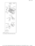
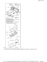
1 Side Case-L Unit
(Fig. D1)
Screw (A) x 5
(Fig. D2)
Screw (B) x 1
Locking tab x 5
Projecting part x 1
Side Case-L Unit
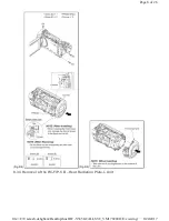
2 Power Panel Light,
SS Button SS Lever ,
Jack Door Spring ,
DC Jack Cover Unit ,
Jack Cover Piece
(Fig. D3)
Power Panel Light
Locking tab x 1
SS Button
Screw (C) x 1
Locking tab x 2
Locking tab x 2
SS Lever
Convex x 4
Jack Door Spring
DC Jack Cover Unit
Jack Cover Piece
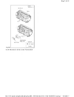
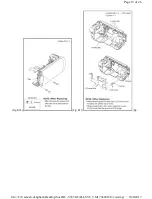
3 Front Case Unit
(Fig. D4)
Screw (D) x 1
Screw (E) x 2
FP6003 (Flex)
Convex x 3
(Fig. D5)
Front Case Unit
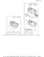
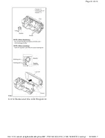
4 Wi-Fi P.C.B.,
Heat Radiation
Plate-L Unit
(Fig. D6)
Flex A
Screw (F) x 1
Wi-Fi P.C.B.
Heat Radiation Plate-L Unit
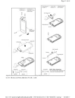
5 Lens Frame Unit
(Fig. D7)
Screw (G) x 1
Screw (H) x 1
P6003 (Connector)
Screw (I) x 2
Projecting part x 1
Locking tab x 2
(Fig. D8)
Lens Frame Unit
6 Camera Lens Unit
(Fig. D9)
FP301 (Flex)
Page 2 of 26
8/24/2017
file://C:\Users\sh.dehghani\Desktop\host\HC-V385GCALLSVC_VM1702001CE\viewing\...

