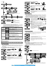

<Threshold value follow-up cycle setting mode>
<External input setting mode>
(OFF)
(Under 60 sec.)
: Select a target value from 0 to 2,000
(100 unit each) to correct the incident
light intensity.
(2,000)
<GETA function setting mode>
(10 to 60 min. or less)
(1 to 9 min. or less)
(OFF)
(SET)
<ECO setting mode>
<Inverting digital display setting mode>
(OFF)
(ON)
(OFF)
(ON)
<Threshold value margin setting mode>
(OFF)
(Green blinks)
(Red blinks)
(Red and Green blink)
Alert output of external
input teaching
Alert output of external input teaching does not
operate unless any of “
”, “
” or “
” is
set at the external input setting mode.
<Setting copy mode>
(YES)
(NO)
(READY)
<Reset mode>
(YES)
(NO)
<RUN mode>
Turn the power off when copying the settings.
: Cancellation is possible when
pressed for 2 sec. or more.
Setting item
Factory setting
Description
Shift setting mode
Shift amount can be selected from 0 to 80% in the limit teaching.
Select 0% when it is desired to set the present incident light intensity as a
threshold value.
External input
setting mode
External input can be selected from emission halt, limit teaching [+], limit
teaching [-], full-auto teaching, ECO (Note 1), 2-point teaching or emission
amount test.
When setting the incident light intensity test “
”, output turns ON / OFF
every 100ms when the rate of incident light intensity and threshold value is less
than half of the set shift amount (for example, when the rate of incident light inten-
sity and threshold value is within ±10% for 20% of shift amount) at external input.
Threshold value-
storing setting mode
(Note 2)
Threshold value set at the limit teaching, full-auto teaching or 2-point teach-
ing by external input is stored. When selecting Auto in the emission amount
setting mode, the set emission amount level is also stored.
Threshold value
follow-up cycle setting
mode (Note 3)
When incident light intensity exceeds threshold value, this mode can change the
threshold value with each set cycle depending on variations of the incident light in-
tensity. The follow-up shift amount is same as the one set in the shift setting mode.
However, the threshold value is not stored.
GETA function setting
mode (Note 4, 5)
Variations can be reduced by correcting the present incident light intensity in
each amplifier to a target value. Target value to offset incident light intensity
can be selected from 0 to 2,000 by 100 unit each.
For example, if the target value is set to 2,000 when the incident light inten-
sity is 1,500, the incident light intensity becomes 2,000.
ECO setting mode
It is possible to light up / turn off the digital display. When ECO setting mode
is ON, the display turns off in approx. 20 sec. in RUN mode. To light up the
display again, press any key for 2 sec. or more.
Inverting digital
display setting mode
Digital display can be inverted.
Threshold value
margin setting mode
Margin for threshold value to the present incident light intensity can be checked.
When there is no margin, it is possible to make the digital display blink.
“
” : Green blinks.
“
”: : Red blinks.
“
” : Red and Green blink.
“
” : When conducting limit teaching or 2-point teaching by external input,
in case the rate of reference incident light intensity and threshold
value after teaching is 200% or more, or in case it is less than half of
the shift amount, output turns ON / OFF every 100ms. (Note 6)
Setting copy mode
The settings of the master side amplifier can be copied to the slave side
amplifier. For details, refer to “
SETTING COPY FUNCTION
.”
Reset mode
Returns to default settings (factory settings).
Notes: 1) When ECO is selected at the external input setting mode, key operation on the main body is invalid during
external input.
2) This mode is not indicated unless any of “
”, “
”, “
” or “
” is set at the external input
setting mode.
3) If the incident light intensity becomes “300” or less, the follow-up operation stops.
In that condition, threshold value [digital display (green)] blinks.
This function can be used when thru-beam type or retroreflective type fiber is applied to this product. If reflec-
tive type fiber is applied, the function cannot be used depending on use conditions.
4) If pressing MODE key in RUN mode when GETA function is used, the incident light intensity before setting
GETA function is displayed on the red digital display for approx. 2 sec.
5) When GETA function is used in saturation of incident light intensity (4,000 or more), “
” is indicated on
the red digital display. Correction value is up to 4,000.)
6) This mode does not operate unless any of “
”, “
” or “
” is set at the external input setting
mode.
9
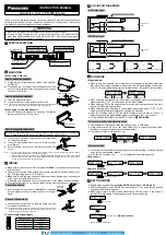
EXTERNAL INPUT SETTING
● When selecting emission halt in the external input setting mode and receiving the
signal externally, “
” is indicated on the red digital display.
● When selecting ECO in the external input setting mode, key operation on the main
body is invalid during external input.
● When selecting 2-point teaching in the external input setting mode, “
” is indi-
cated on the green digital display after inputting the first point.
● For the setting of external input, refer to “
PRO MODE
.”
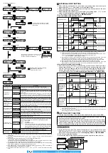
<Time chart when setting external input>
External input signal
Emisson halt
(Note 1)
Limit
teaching
Full-auto
teaching
(Note 4)
ECO mode
2-level
teaching
25ms or more
20ms or more
20ms
(Note 2)
Emission
NPN output
type: Low
High
Low NPN output
type: High
20ms
20ms
20ms
Emission halt
20ms
20ms
Teaching in progress
Normal operation
20ms
Teaching in progress
Sampling in
progress
20ms
20ms
20ms
Normal operation
20ms
20ms
20ms
20ms
ECO in progress
Normal operation
20ms
First point
Second point
20ms
Teaching in progress
Normal operation
(Note 3)
(Note 5)
(Note 2)
Notes: 1) Output may turn ON / OFF when emission is halted or is released depending on setting of threshold value.
2) When emission starts, output operation will be undetermined only during the response time.
If the output signal is received by something such as a PLC, set the timer to a value of 20ms amplifier response time or greater.
Example: For the
FX-101
□
-Z
with emission frequency 0 (response time 250µs or less)
Timer period: 20ms + 0.25ms (250µs) = 20.25ms
3) After teaching is complete, output operation will be undetermined only during the response time. If the output
signal is received by something such as a PLC, set the timer to the amplifier response time or greater.
The threshold value will be set based on the incident light intensity at the instant when teaching is verified.
4) Move the sensing object past once during the time that the external input signal is being input.
5) After teaching is complete, output operation will be undetermined only during the response time. If the output
signal is received by something such as a PLC, set the timer to the amplifier response time or greater.
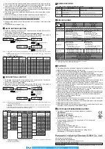
<Alert output of external input teaching>
● When conducting limit teaching or 2-point teaching by external input, if the alert output of
external input teaching “
” is set in the threshold value margin setting mode, output
turns ON / OFF every 100ms in case the rate of reference incident light intensity and thresh-
old value after teaching is 200% or more, or in case it is less than half of the shift amount.
For the setting method, refer to <
Threshold value margin setting mode
> under “
PRO MODE
.”
External input signal
25ms or more
20ms or more
High
Low
NPN output
type: Low
NPN output
type: High
Limit teaching
20ms
20ms
Teaching in progress
Normal operation
Output operation
when selecting
alert output of
external input
teaching
“
”
100ms
100ms
(Note 1)
(Note 1)
100ms
100ms
ON
OFF
2-level teaching
20ms
First point
20ms
Second point
Teaching in progress
Normal operation
ON
OFF
(Note 2)
Output operation
when selecting
alert output
of external
input teaching
“
”
100ms
100ms
Notes: 1) In case the margin is no good, output turns ON / OFF every 100ms during the time that the external input
signal is being input after teaching.
2) In case the margin is no good, output turns ON / OFF every 100ms during the time that the external input
signal is being input after the second teaching.
10
SETTING COPY FUNCTION
● This can copy the settings of the master side amplifier to the slave side amplifier.
● Be sure to use the setting copy function between the identical models. This func-
tion cannot be used between different models.
● Only one sensor can be connected on slave side with a master side sensor for the setting copy function.
● Threshold value, output operation setting, timer operation setting, timer setting, emission
amount setting, shift setting, external input setting, threshold value-storing setting, ECO
setting, inverting digital display setting, and threshold value margin setting can be copied.
Setting procedures
1.
Set the setting copy mode of the master side amplifier to “Copy sending ON,” and press
MODE key so that “
” is shown on the digital display and the sensor is in copy
ready state. For the setting method, refer to <
Setting copy mode
> in “
PRO MODE
.”
2.
Turn off the master side amplifier.
3.
Connect the master side amplifier with the slave side amplifier as shown below.
Color code of cable with connector
(White)External input
(Brown)+V
(Black)Input
(Blue)0V
Master side amplifier
Slave side amplifier
(White)External input
(Brown)+V
(Black)Input
(Blue)0V
Power supply
www.digiparts.ch
Ihr Schweizer Industriepartner