


9
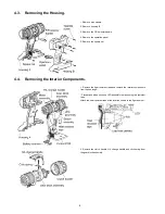
4.5.
Removing the Switch Assembly, LED Assembly and Battery Terminal.
4.6.
Removing the Gear Case Assembly from the Module Assembly.
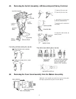
1. Remove the 2-pin connector.
2. Remove the 6-pin connector.
3. Pull the faston terminal directly
out from the switch assembly.
* Exercise care not to bend the ter-
minal fitting.
4. Remove the lead wires from the
battery terminal.
Connecting and disconnecting the connector
* Precautions when attaching the connectors
Holding the motor assembly, remove the entire motor mounting plate,
including the gear box assembly from the motor assembly.
Summary of Contents for EY74A2
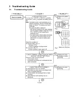
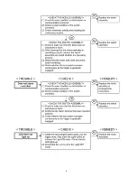
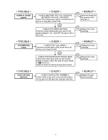
Page 3: ...3 3 Troubleshooting Guide 3 1 Troubleshooting Guide ...
Page 4: ...4 ...
Page 5: ...5 ...
Page 12: ...12 4 10 Wiring and Assembly Points ...
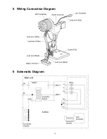
Page 13: ...13 5 Wiring Connection Diagram 6 Schematic Diagram ...
Page 14: ...Model No EY74A2 Exploded View ...