background image

16

7.2.

REPLACEMENT PARTS LIST

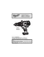
MODEL No.EY7451

Safety

Ref. No.

Part No.

Part Name & Description

Q'ty

Remarks

1

WEY7451K3078

HOUSING AB SET

1

2

WEY6450L6808

CHUCK FASTENING SCREW

1

3

WEY7441K7917

KEYLESS CHUCK

1

4

WEY7441H3227

CLUTCH HANDLE

1

5

WEY7441L0637

ADJUSTING SCREW

1

6

WEY7441L0177

CLUTCH SPRING

1

7

WEY7441L0577

CLUTCH PLATE

1

8

WEYT107L0457

CLICK SPRING A

1

9

WEY7460H3237

H/L CHANGE HANDLE

1

10

WEY7460H3248

F/R SELECTOR HANDLE

1

11

WEY7441L6968

STEEL BALL

12

(

5)(12PCS/PK)

12

WEY7441L1088

DRIVING BLOCK

1

13

WEY7441L1138

CARRIER

1

14

WEY7441L1428

RING GEAR

1

15

WEY7441L1348

PLANET GEAR

6

(3PCS/PK)

16

WEY7441L0858

THRUST PLATE

1

(

37.95)

17

WEY7441L1118

CARRIER

1

18

WEY7441L0268

STOPPPER

1

19

WEY7441L1768

GEAR CASE

1

20

WEY7441K9628

TAPPING SCREW

4

(K3-12)

21

WEY7441L1458

RING GEAR A

1

22

WEY7441L1128

CARRIER B

1

23

WEY7441L1468

RING GEAR B

1

24

WEY7441L1368

PLANET GEAR B

3

(3PCS/PK)

25

WEY7441L0888

THRUST PLATE

1

37.8

26

WEY7441L4057

GEAR BOX BLOCK

1

27

WEY7451L1008

MOTOR ASSEMBLY

1

28

WEY7441L2579

MOTOR BRUSH ASSEMBLY

1

29

WEY7441L0128

FIXING PLATE

1

30

WEY7441L2007

SWITCH ASSEMBLY

1

31

WEY7441L6028

SCREW

2

(K3-6)

32

WEY7441L0378

ROLLER SET

6

(

3.175*7.2)(6PCS/PK)

33

WEY7451L2118

WATERPROOF CIRCUIT ASSEMBLY

1

34

WEY7451K3958

OPERATION PANEL

1

35

WEY7543K3187

PLATE HOOK

1

36

WEY7441L6487

NUT

1

(M4)

37

WEY7441K6217

SCREW

1

(4-14)

38

WEY7441K9038

TAPPING SCREW

8

(K3-20)

 -

WEY9633K7010

TOOL CASE

1

 -

WEY7441K81P0

OPERATING INSTRUCTIONS

1

Summary of Contents for EY7451

Page 1: ...2 1 EY7451 MAIN UNIT 2 2 2 MAXIMUM RECOMMENDED CAPACITIES 2 3 Troubleshooting Guide 3 3 1 Trial Operation after checking Troubleshooting Guide 6 4 Disassembly and Assembly Instructions 7 4 1 How to disassemble Plate hoot and Keyless chuck 7 4 2 How to disassemble Main unit 8 5 Wiring Connection Diagram 13 6 Schematic Diagram 14 7 Exploded View and Replacement Parts List 15 7 1 PARTS LOCATION 15 7 ...

Page 2: ...heated too high about 1100 F 600 C 2 Specifications 2 1 EY7451 MAIN UNIT 2 2 MAXIMUM RECOMMENDED CAPACITIES Motor 18V DC No load speed LOW 70 400 min rpm HIGH 200 1400 min rpm Chuck capacity 1 5 13mm 1 16 1 2 Macimum torque Stalling torque 3 0Ah Li ion Battery Clutch torque Approx 0 5Nm 5 0kgf cm 4 3in lbs 4 4Nm 45 Okgf cm 39 0in lbe Overall length 193mm 7 5 8 Weight with battery pack EY9L53 1 65k...

Page 3: ...3 3 Troubleshooting Guide Refer to Wiring Connection Diagram ...

Page 4: ...4 ...

Page 5: ...5 ...

Page 6: ... Confirm if LED rights ON Once battery pack is removed press the switch handle otherwise LED does not right ON 3 Confirm if the tools may not become hot in a short operation 4 Confirm the action when setting the DRILL mode 5 Confirm if the chuck jaws move smoothly and hold the bit firmly 3 1 3 SWITCH 1 Confirm the rotation of speed if it changes between 200 1400 140 rpm in proportion to the amount...

Page 7: ...collar counterclockwise looking from the front to open the chuck jaws 3 Use a screwdriver to turn the chuck fastening screw inside the chuck clockwise direction of the arrow and remove the screw NOTE If the chuck fastening screw will not come loose insert the allen wrench into the chuck and lightly tap in the clockwise direction with a hammer to tighten the chuck and then loosen the chuck fastenin...

Page 8: ...emove 8 housing screws 4 2 2 Removal of Motor screw Removal 1 Remove 2 screws 4 2 3 Removal of Switch and Driving block Removal 1 Take out the switch assembly 2 Take out the driving block 3 Separate the motor from the gear box block by twisting the motor to unlock tabs ...

Page 9: ...oval or attachment of the Gear Box Block Removal 1 Turn the thrust plate to remove 2 The internal parts of gear box block can be removed one after another Attachment 1 Start from inserting 6 pins into the driving block as shown in the figure 2 Assemble the other parts in reverse order as shown in the figure NOTE Carriers and Ring Gears have their own correct directions for proper reassembly ...

Page 10: ...ew has its own correct direction for proper assembly Failure to do so the clutch handle does not rotate properly 2 Turn the adjusting screw into the driving block about one rotation for clockwise direction 3 Set the clutch handle with position 1 on top Align the position 1 of clutch handle with the narrow pro jection of driving block 4 Insert the clutch handle with adjusting the tabs of adjust ing...

Page 11: ...11 4 2 7 Attachment of the H L change han dle 1 Insert the both side of handle spring into the groove of Ring gear A ...

Page 12: ...12 4 2 8 Assemble of Driving block ...

Page 13: ...13 5 Wiring Connection Diagram ...

Page 14: ...14 6 Schematic Diagram ...

Page 15: ...15 7 Exploded View and Replacement Parts List 7 1 PARTS LOCATION 1 1 4 8 9 5 6 7 3 2 10 35 36 37 11 12 32 14 13 15 16 28 31 31 29 30 33 38 38 38 38 38 38 38 38 27 25 24 22 23 21 15 17 19 20 26 18 34 ...

Page 16: ...8 THRUST PLATE 1 37 95 17 WEY7441L1118 CARRIER 1 18 WEY7441L0268 STOPPPER 1 19 WEY7441L1768 GEAR CASE 1 20 WEY7441K9628 TAPPING SCREW 4 K3 12 21 WEY7441L1458 RING GEAR A 1 22 WEY7441L1128 CARRIER B 1 23 WEY7441L1468 RING GEAR B 1 24 WEY7441L1368 PLANET GEAR B 3 3PCS PK 25 WEY7441L0888 THRUST PLATE 1 37 8 26 WEY7441L4057 GEAR BOX BLOCK 1 27 WEY7451L1008 MOTOR ASSEMBLY 1 28 WEY7441L2579 MOTOR BRUSH ...

Reviews: