background image

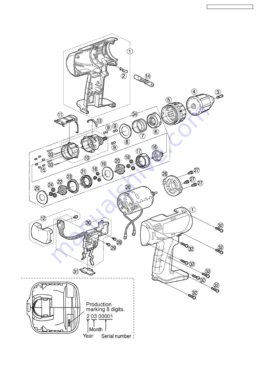
5 EXPLODED VIEW

9

EY6405-X8 / EY6409-X8 / EY6432-X8

Summary of Contents for EY6405-X8

Page 1: ...002 Matsushita Electric Works Ltd All rights reserved Unauthorized copying and distribution is a violation of law EY6405 X8 EY6409 X8 EY6432 X8 4 TROUBLESHOOTING GUIDE 7 5 EXPLODED VIEW 9 6 REPLACEMENT PARTS LIST 10 Cordless Drill Driver SPECIFICATIONS CONTENTS Page Page ORDER NO PTD0207X34C8 ...

Page 2: ...1 SCHEMATIC DIAGRAM 2 WIRING CONNECTION DIAGRAM 2 1 EY6405 EY6409 2 2 EY6432 2 EY6405 X8 EY6409 X8 EY6432 X8 ...

Page 3: ... chuck fastening screw inside the chuck clockwise direction of the arrow and remove the screw See Fig 1 NOTE If the chuck fastening screw will not come loose insert the allen wrench into the chuck and lightly tap in the clockwise direction with a hammer to tighten the chuck and then loosen the chuck fastening screw See Fig 2 4 Insert the allen wrench into the chuck and turn counterclockwise direct...

Page 4: ...ig 4 Fig 5 Ref No 2B Procedure 2A 2B Removal or attachment of the Motor Fig 6 Removal 1 Take out the motor with the gear box block from housing 2 Separate the motor from the gear box block by twisting the motor to unlock tabs Attachment 3 Motor mounting base and the positioning rib of gear case should be set See Fig 6 4 EY6405 X8 EY6409 X8 EY6432 X8 ...

Page 5: ...ther See Fig 7 Attachment 3 If the lock ring comes out reassemble in the correct direction See Fig 8 4 Start from inserting 6 pins into the driving block as shown in the Fig 9 5 Assemble the other parts in reverse order as shown in the Fig 7 NOTE Carrier Carrier A and B Ring Gear and Ring Gear A have their own correct directions for proper reassembly 5 EY6405 X8 EY6409 X8 EY6432 X8 ...

Page 6: ... 2 Turn the adjusting screw into the driving block about one rotation for clockwise direction 3 Align the mark of adjusting screw with the center of upper projection of clutch case 4 Set the clutch handle with position 1 on top 5 Insert the clutch handle with adjusting the tabs of adjusting screw to the groove of inside clutch handle Fig 11 6 EY6405 X8 EY6409 X8 EY6432 X8 ...

Page 7: ...OK CHECK TERMINAL CONNECTIONS BETWEEN MAIN UNIT NO repair contacts AND BATTERY PACK Check for proper terminal contacts OK CHECK SWITCH BLOCK NO Contacts in switch block See WIRING CONNECTION DIAGRAM are defective Check continuity between following terminals Replace switch FET Inspection of the forward reverse selection switch block When switch handle is depressed all the way There should be 0Ω bet...

Page 8: ...ove the FET circuit block and check the lead wire terminals These terminals are open normally when there is an open circuit Ω between the green and yellow lead wires and between the blue and yellow lead wires NOTE FET is sensitive against static electricity The resistance value will vary dependent upon the measurement range of the tester OK CHECK SWITCH BLOCK NO Replace switch FET block 8 EY6405 X...

Page 9: ...5 EXPLODED VIEW 9 EY6405 X8 EY6409 X8 EY6432 X8 ...

Page 10: ... 17 WEY6406L1488 RING GEAR 1 18 WEY6406L1348 PLANET GEAR B 3pcs PK 6 19 WEY6406L0858 THRUST PLATE 1 20 WEY6406L1128 CARRIER A 1 21 WEY6406L1468 RING GEAR A 1 22 WEY6406L1108 CARRIER B 1 23 WEY6406L1478 RING GEAR B 1 24 WEY6406L1358 PLANET GEAR B B 3pcs PK 3 25 WEY6406L0888 THRUST PLATE 1 26 WEY6405L1008 DC MOTOR 1 27 WEY6230L6027 SCREW C K3 6 3 28 WEY6406L0028 MOTOR MOUNTING PLATE 1 29 WEY6207Y602...

Page 11: ...488 RING GEAR 1 18 WEY6406L1348 PLANET GEAR B 3pcs PK 6 19 WEY6406L0858 THRUST PLATE 1 20 WEY6406L1128 CARRIER A 1 21 WEY6406L1468 RING GEAR A 1 22 WEY6406L1108 CARRIER B 1 23 WEY6406L1478 RING GEAR B 1 24 WEY6406L1358 PLANET GEAR B B 3pcs PK 3 25 WEY6406L0888 THRUST PLATE 1 26 WEY6405L1008 DC MOTOR 1 27 WEY6230L6027 SCREW C K3 6 3 28 WEY6406L0028 MOTOR MOUNTING PLATE 1 29 WEY6207Y6027 SCREW C K3 ...

Page 12: ...488 RING GEAR 1 18 WEY6406L1348 PLANET GEAR B 3pcs PK 6 19 WEY6406L0858 THRUST PLATE 1 20 WEY6406L1128 CARRIER A 1 21 WEY6406L1468 RING GEAR A 1 22 WEY6406L1108 CARRIER B 1 23 WEY6406L1478 RING GEAR B 1 24 WEY6406L1358 PLANET GEAR B B 3pcs PK 3 25 WEY6406L0888 THRUST PLATE 1 26 WEY6432L1008 DC MOTOR 1 27 WEY6230L6027 SCREW C K3 6 3 28 WEY6406L0028 MOTOR MOUNTING PLATE 1 29 WEY6207Y6027 SCREW C K3 ...

Reviews: