


859
Leak Detection Sensor
EX-F70
SERIES
EX-F60
SERIES
FIBER
SENSORS
LASER
SENSORS
PHOTO-
ELECTRIC
SENSORS
MICRO
PHOTO-
ELECTRIC
SENSORS
AREA
SENSORS
LIGHT
CURTAINS
PRESSURE /
FLOW
SENSORS
INDUCTIVE
PROXIMITY
SENSORS
PARTICULAR
USE
SENSORS
SENSOR
OPTIONS
SIMPLE
WIRE-SAVING
UNITS
WIRE-SAVING
SYSTEMS
MEASURE-
MENT
SENSORS
STATIC
CONTROL
DEVICES
ENDOSCOPE
LASER
MARKERS
PLC /
TERMINALS
HUMAN
MACHINE
INTERFACES
ENERGY
CONSUMPTION
VISUALIZATION
COMPONENTS
FA
COMPONENTS
MACHINE
VISION
SYSTEMS
UV
CURING
SYSTEMS
Selection
Guide
Wafer
Detection
Liquid Leak
Detection
Liquid Level
Detection
Water
Detection
Color Mark
Detection
Hot Melt Glue
Detection
Ultrasonic
Small / Slim
Object Detection
Obstacle
Detection
Other
Products
SQ4
EX-F70/
EX-F60
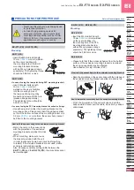
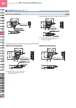
PRECAUTIONS FOR PROPER USE
Refer to General precautions.
EX-FC1
Mounting
• When mounting the unit, be sure to use the unit mounting
base (
MS-SL-2
) (accessory).
• When installing the unit mounting base to the unit, insert
the base aligned with the grooves of the unit and move
until the unit stopper is locked.
• Two installation positions are available for the unit
mounting base so that the unit direction can be changed.
Install the base at one of them.
Mounting position 1
Mounting position 2
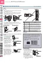
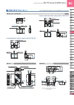
˂In case of using a DIN rail or the mounting bracket (MS-DIN-3)
(optional)˃
Fit the rear part of the unit
mounting base on a 35 mm
1.378 in
width DIN rail or
the mounting bracket
(
MS-DIN-3
) (optional).
Press down the front part
of the unit mounting base
on the 35 mm
1.378 in
width DIN rail and fit the
front part of the base on
the DIN rail.
* For removal, insert a
flathead screwdriver into
the DIN rail stopper and
pull towards yourself.
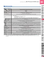
Designation
Function
Normal indicator
(Green LED × 8)
Lights up when sensors are connected to each channel
and the connection setting switch is set to ON.
Error indicator
(Red LED × 8)
Lights up when leak is detected by any sensor
connected or any sensor is mounted improperly.
(For details, refer to “
Connection setting switch
”.)
Output indicator
(Orange LED)
Lights up when the output relay is ON (Normal).
Connection setting
switch
Set the switch to ON when the leak detection
sensor is connected, set to OFF when the leak
detection sensor is not connected.
Connector
Connect the leak detection sensors.
Part description
Grooves
Unit stopper
Unit
Unit mounting base
Din rail stopper
7
6
5
4
3
2
1
0
Unit
Unit mounting base
Din rail stopper
DIN rail stopper
35 mm
1.378 in
width DIN rail or the
mounting bracket (
MS-DIN-3
) (Optional)
Flathead screwdriver
DIN rail stopper
Unit stopper
Unit mounting
base
Unit
(
Purchase
separately.
M4 pan head screw
)
④
①
③
②
⑤
7
6
5
4
3
2
1
0
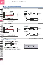
Connection method
• Make sure to connect or disconnect the snap male
connector (
SL-CP1
) in the power supply off condition.
• Take care that wrong wiring will damage the product.
• The terminal No. 4 of the snap male connector
(
SL-CP1
) is not used.
Take care not to connect to the terminal No. 4 by
mistake. Further, if there are unused wires, please
insulate them.
1 2 3 4
1 2 3 4
Content
+V
0 V
IN
No connected
• For details of the hook-up method of the snap male
connector (
SL-CP1
), refer to the Instruction Manual
enclosed with
SL-CP1
.
• By holding the
SL-CP1
with
the cable connected, insert it
into the connector of the
EX-FC1
reliably till it stops.
Disconnection method
•
By holding
SL-CP1
, pull it
from the
EX-FC1
horizontally.
Note: Do not pull out by holding the
cable, as this can result in cable
disconnection.
7
6
5
4
3
2
1
0
EX-FC1
SL-CP1
(Accessory)
Cable of the leak
detection sensor
Connection
˂In case of using screws˃
• Mount using M4 pan head
screws with a tightening
torque of 0.8 N·m or less.
However, in case of side
mounting, make sure to
mount the unit such that
the unit stopper faces
front.