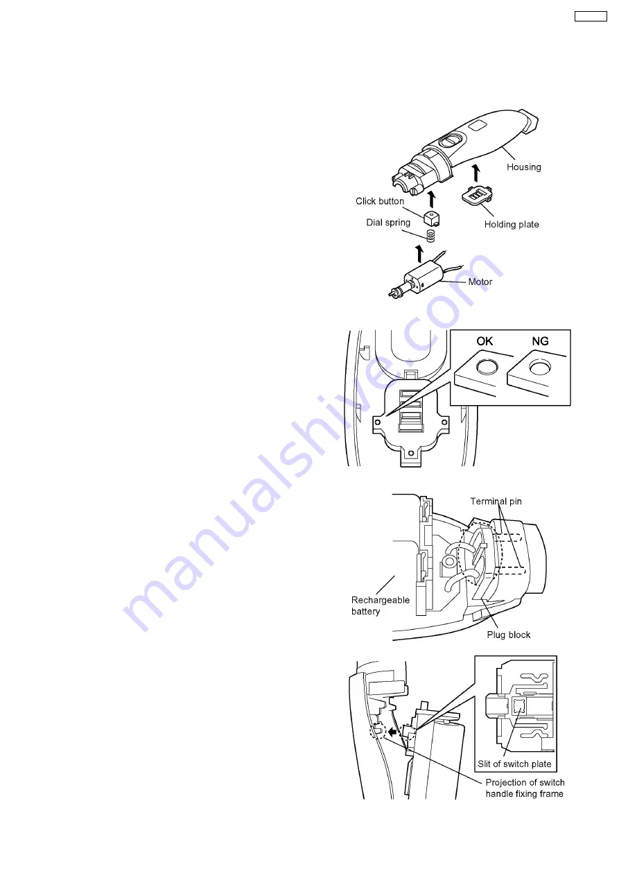
1. Set the click button and the dial spring to the housing A.
2. Place the holding plate on the housing A firmly.
NOTE: Confirm if housing bosses completely cover the
hole of holding plate.
3. Insert the terminal pins into the hole of housing A firmly and
set the battery & module assembly into the housing A.
NOTE: Confirm to set the switch handle OFF position.
And make sure that the projection of switch handle
fixing frame connects to the slit of switch plate.
NOTE: Confirm the smooth movement and operation of
switch handle.
4 ASSEMBLY INSTRUCTIONS
NOTE: Always set the dial to "2.0mm" when removing or attaching the blade; otherwise the blade can not be attached.
Always set the dial to "0.8mm" when removing or attaching the comb attachment.
5
ER154-E8


