3 TROUBLESHOOTING GUIDE
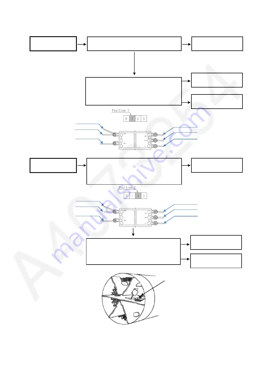
Refer to WIRING CONNECTION DIAGRAM.
< TROUBLE >
< CHECK >
< REMEDY >
Main Body does not
operate
<CHECK POWER CORD>
Check the conductivity of POWER CORD.
<CHECK MAIN SWITCH>
Check the conductivity between the terminal 1
and 4 by setting the main switch at Position 1.
(Figure 1)
Replace the MAIN
SWITCH
Replace the MOTOR
HEATER ASSEMBLY
NG
Figure 1
OK
NG
OK
Hot Air is not emitted
<CHECK MAIN SWITCH>
Check the conductivity between the terminal 2
and 4 by setting the main switch at Position 2
(Figure 2)
Replace the MAIN
SWITCH
NG
OK
Figure 2
<CHECK HEATER BLOCK>
Check if there are foreign objects on the joint
of the thermo switch (Figure 3)
Remove the foreign
objects on the joints
OK
NG
Replace the MOTOR
HEATER ASSEMBLY
Replace the MOTOR
HEATER ASSEMBLY
Thermo switch
Lead Wire ( Violet
)
Lead Wire ( Brown)
Lead Wire ( White)
Lead Wire ( Green
)
Lead Wire ( Brown-Cod)
Lead Wire ( Violet)
Lead Wire ( Brown)
Lead Wire ( White)
Lead Wire ( Green)
Lead Wire ( Brown-Cod)
Figure 2
Lead Wire ( Black)
Lead Wire ( Black)


