15
9.5.
Optical pick-up unit
9.5.1.
Removing optical pick-up unit
Make sure that the traverse assembly removed before trying to
remove the optical pick-up unit.
When removing the traverse assembly, solder the one laser
short land on the flexible cable of the optical pick-up unit.
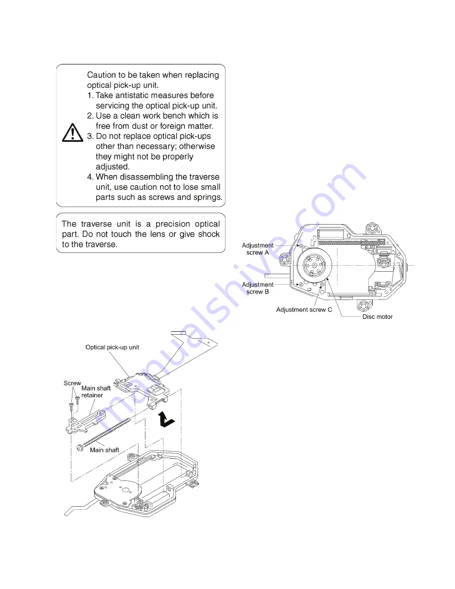
1. Remove the two screws securing the main shaft retainer.
2. Remove the main shaft retainer.
3. Slide the main shaft in the direction indicated by the arrow
to remove the optical pick-up unit.
9.5.2.
Reinstalling optical pick-up unit
The optical pick-up unit is factory adjusted. Do not touch the
adjustment screw.
1. Reassemble the disassembled parts in the reverse order
of disassembly.
2. When reinstalling the traverse assembly on the main unit
after installing the optical pick-up unit, make sure to
remove the solder from each of the two laser short lands
on the flexible cable.
Caution:
• Remove the solders completely; otherwise the laser diode
won't emit light.
• After replacing the optical pick-up unit, check the quality of
images played back and make optical adjustment.
9.6.
Disc motor
9.6.1.
Removing disc motor
1. Remove the adjustment screws A, B, and C.
2. Remove the disc motor.
9.6.2.
Caution to be taken when replacing
the disc motor
1. The mounting screws of the disc motor also serve as
adjustment screws. When reinstalling the disc motor, first
turn the screws A, B, and C as far as they go by usual
force to secure them (do not overtighten).
2. Back off the adjustment screws A and C two complete
turns and secure them.
3. Back off the adjustment screw B one and a half turns and
secure them.
• This makes it nearly possible to play back disks and
adjust the jitter.
Thereafter, adjust the adjustment screws C and A as
indicated.


