


1
2
3 4
7
6
5
BS AUDIO board
21
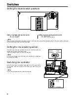
Switches
POWER
MAKE
G tally selector switch (SW201)
Refer to the diagram at right and
select the desired switch position.
4
–20dB
0dB
MIC1 selector switch (SW203)
Refer to the diagram at right and
select the desired switch position.
6
–20dB
0dB
MIC2 selector switch (SW204)
Refer to the diagram at right and
select the desired switch position.
7
Switches 1 and 2 are used to connect the intercom system
using the COMMUNICATION connector (see page 7). For
details on the settings, refer to the intercom system selection
table below.
POWER
MAKE
R tally selector switch (SW200)
Refer to the diagram at right and
select the desired switch position.
3
4W
RTS
2W
2-lines / RTS / 4-lines
selector switch (SW1)
1
Intercom system
SW1
SW2
2W (two-wire system)
ON
2W
4W (four-wire system)
ON (Note 1) 4W (Note 1)
RTS system
OFF (Note 2) RTS
Note 1: When the unit is not going to be connected to the intercom
system, set SW1 to ON and SW2 to 4W. (These are the factory
settings.)
Note 2: When there is absolutely no RTS load in the entire intercom
system, set SW1 to ON and use the RTS load function inside the
unit.
Intercom system selection table
Setting the board switch positions
<Note>
The diagrams show the factory settings.
ENG RTS LOAD ON/OFF
switch (SW3)
ON
OFF
2
0dB
–20dB
PGM1 selector switch (SW202)
Refer to the diagram at right and
select the desired switch position.
5
Summary of Contents for DVCPRO AJ-BS901EN
Page 25: ...25 ...