background image

10

VQT5K48 (ENG)

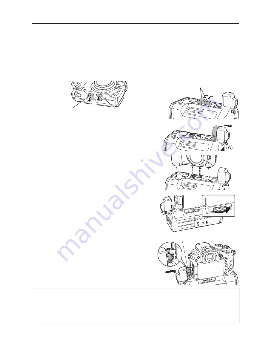
Mounting to the Digital Camera

y

y

Make sure that a DC power supply is not connected to the unit’s DC IN terminal and that the 

digital camera is turned off. 

(Mounting or dismounting while the power is on may result in malfunction.)

Remove the cover for the battery grip connector and cover for the interface unit 

connector on the digital camera, and 

 remove the electrical contact and interface 

contact caps on the unit.

y

y

Store the connector covers and contact caps safely to avoid loss.

y

y

To protect the terminals, reattach the covers and caps after you finish using the unit.

Cover for the battery grip 

connector

Cover for the interface unit 

connector

Terminal caps

Loosen the HDMI connection terminal screw (A), 

and slide the HDMI connection terminal out to the 

side.

y

y

Do not twist or pull the HDMI connection terminal with 

excessive force. Doing so may result in malfunction 

or damage.

Align the attachment screw, contacts, and camera 

attachment pins, and attach the digital camera.

Rotate the attachment screw (B) in the direction of 

the arrow and tighten it securely.

y

y

Verify that the attachment screw is tightened securely 

during use.

Open the terminal cover on the digital camera, slide 

the HDMI connection terminal on the unit inward 

(toward the camera) to connect it, and tighten the 

HDMI connection terminal screw (A) securely.

y

y

Open the terminal cover on the digital camera 90 

degrees, and store it in the HDMI connection terminal.

(B)

Terminal cover

90°

(A)

„

„

Dismounting from the digital camera

y

y

Make sure that a DC power supply is not connected to the unit’s DC IN terminal and that 

the digital camera is turned off, and then perform the mounting procedure in reverse order 

(disconnect the HDMI connection terminal before rotating the attachment screw (B)). 

Performing the procedure in the incorrect order may result in damage.

Summary of Contents for DMW-YAGHPP

Page 1: ...FJ Owner s Manual Interface Unit Model No DMW YAGHPP Please read these instructions carefully before using this product and save this manual for future use PP If you have any questions visit USA www panasonic com support ...

Page 2: ...side Refer servicing to qualified service personnel CAUTION In order to maintain adequate ventilation do not install or place this unit in a bookcase built in cabinet or any other confined space To prevent risk of fire hazard due to overheating ensure that curtains and any other materials do not obstruct the ventilation CAUTION To reduce the risk of fire and annoying interference use the recommend...

Page 3: ... Do not lift the unit or the camera with a tripod attached The additional weight on the unit from the attached tripod may damage the connection between the unit and the camera and may result in injuries When a tripod is attached always carry the equipment by the tripod indicates safety information ...

Page 4: ...ll not occur in a particular installation If this equipment does cause harmful interference to radio or television reception which can be determined by turning the equipment off and on the user is encouraged to try to correct the interference by one of the following measures Reorient or relocate the receiving antenna Increase the separation between the equipment and receiver Connect the equipment ...

Page 5: ...ut XLR is supported with audio level meters available You can also input an external timecode to be used as a reference signal y yWhen the unit is mounted on a digital camera the electronic sound and electronic shutter sound of the digital camera are disabled Contents Read this first 2 Accessories 7 Names and Functions of Components 8 Mounting to the Digital Camera 10 Switching the Video Output 11...

Page 6: ...ouble in operation or malfunctioning In direct sunlight or on a beach in summer In locations with high temperatures and humidity levels or where changes in temperature and humidity are acute Where there is fire Near heaters air conditioners or humidifiers Where there is vibration Inside a vehicle y yPlease also read the manual of your digital camera y yPanasonic will not be liable for any direct o...

Page 7: ... y yBe sure to dispose of the packaging materials in an appropriate manner after unpacking the unit y yThe following supplied accessories come attached to the unit Terminal cap electrical contacts Terminal cap interface contacts ...

Page 8: ...rame GND Notes on DC power supply battery y yVerify that the output voltage matches the unit s voltage rating before connection y yUse a rated output current that is equal to or higher than the unit s input current rating y yUse a shielded cable that is less than 2 m in length for the DC cable connecting the unit to the DC power supply battery y yAn inrush current is generated when the digital cam...

Page 9: ...rnal microphone is connected Input level 50 dBu 48V When a phantom microphone a microphone that requires a 48 V power supply is connected A power supply of 48 V will be provided to the AUDIO IN CH1 and AUDIO IN CH2 terminals 13 STEREO MONO switch Switches the audio that is input to the AUDIO IN CH1 and AUDIO IN CH2 terminals to stereo or monaural audio STEREO Two channel stereo audio MONO Monaural...

Page 10: ...nection terminal with excessive force Doing so may result in malfunction or damage 3 Align the attachment screw contacts and camera attachment pins and attach the digital camera 4 Rotate the attachment screw B in the direction of the arrow and tighten it securely y yVerify that the attachment screw is tightened securely during use 5 Open the terminal cover on the digital camera slide the HDMI conn...

Page 11: ...o playback mode videos and menus will not be displayed in the camera s monitor Press the Fn3 button in such cases to switch the video output destination to the digital camera and display videos and menus in the camera s monitor Press the Fn3 button again to switch the video output destination to the unit Fn3 ...

Page 12: ...s AUDIO IN CH1 CH2 terminals When this is selected the Lens Noise Cut setting will be fixed at OFF SDI Remote Recording Select whether to output control information for recording start stop to the external equipment connected to this unit s SDI OUT terminals y y ON Enable the function y y OFF Disable the function LED Brightness Specify the brightness of the level meters y y HIGH LOW 3G SDI Type Se...

Page 13: ...gital camera Setup Motion Picture TV Connection y yHDMI Mode Play When AUTO is selected the output resolution is set automatically based on the recorded format resolution When a setting other than AUTO is selected timecodes are not superimposed on SDI outputs y y3D Playback Fixed at 2D y yVIERA Link Fixed at OFF HDMI Rec Output y y4K Down Convert AUTO cannot be selected Additional Menus continued ...

Page 14: ... 98p FHD 1920 1080 59 94p 3G SDI Level A B 1920 1080 50p 3G SDI Level A B 1920 1080 59 94i 1920 1080 50i 1920 1080 24PsF 1920 1080 23 98PsF HD 1280 720 59 94p 1280 720 50p Sampling Y Cb Cr 4 2 2 Bit depth 8 bit 10 bit Digital audio Sampling frequency 48 kHz video sync Quantization 16 bit Headroom 12 dB Input output TC IN BNC 1 1 0 V p p to 4 0 V p p 10 kΩ AUDIO IN XLR 3 pin 2 high impedance LINE M...

Page 15: ...duct or c refund your purchase price The decision to repair replace or refund will be made by the warrantor Product or Part Name Parts Labor Interface Unit 1 Year 1 Year All included Accessories Except Non Rechargeable Batteries 90 Days Not Applicable Only Non Rechargeable Batteries 10 Days Not Applicable During the Labor warranty period there will be no charge for labor During the Parts warranty ...

Page 16: ... RECEIPT PROOF OF PURCHASE INDICATING DATE OF PURCHASE AMOUNT PAID AND PLACE OF PURCHASE CUSTOMER WILL BE CHARGED FOR THE REPAIR OF ANY UNIT RECEIVED WITHOUT SUCH PROOF OF PURCHASE Limited Warranty Limits And Exclusions This warranty ONLY COVERS failures due to defects in materials or workmanship and DOES NOT COVER normal wear and tear or cosmetic damage The warranty ALSO DOES NOT COVER damages wh...

Page 17: ...r dealer or Service Center If the problem is not handled to your satisfaction then write to the warrantor s Consumer Affairs Department at the addresses listed for the warrantor PARTS AND SERVICE WHICH ARE NOT COVERED BY THIS LIMITED WARRANTY ARE YOUR RESPONSIBILITY Customer Services Directory United States Obtain Product Information and Operating Assistance locate your nearest Dealer or Service C...

Page 18: ...Panasonic Corporation of North America Two Riverfront Plaza Newark NJ 07102 5490 Panasonic Corporation 2014 Printed in China ...

Reviews: