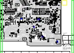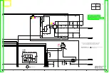
G_IIC_CLK_A
G_YOUT_DM_A
G_IIC_DATA_A
G_COUT_DM_A
SYNC_DET
G_CIN_DM_A
R4005
820
G_AADC_R_A
G_SLICER_A
G_V_YIN_DM_A
R4003
820
G_AADC_L_A
G_CSYNC_A
AV2_BLANKING
LB3001
J0JGC0000020
G_RPROUT_D_A
G_BPBOUT_D_A
G_GPYOUT_D_A
PS_11R6V
PS_5V
T
M
M
T
M
M
M
M
T
M
M
T
T
M
T
M
M
A
B
1
2
3
4
5
6
7
8
9
10
11
12
13
14
15
16
17
18
20
19
21
22
5
4
3
2
1
B
TO
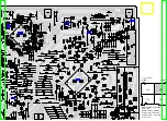
A/V I/O SECTION
(1/4)
NOTE:DO NOT USE THE PART NUMBER SHOWN ON THIS DRAWING FOR ORDERRING.
THE CORRECT PART NUMBER IS SHOWN IN THE PARTS LIST,AND MAY BE
SLIGHTLYDIFFERNT OR AMENDED SINCE THIS DRAWING WAS PREPARED.
DMR-EH55EC/EP,EH56EG
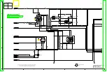
A/V I/O(3/4) Section
(Main P.C.B.(2/4))
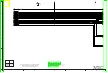
Schematic Diagram(AV)
DE:Nicam Decoder Section:(Page: )
C
LOCATION MAP
1/4
2/4
3/4
4/4
Summary of Contents for DMR-EH55EC
Page 7: ...3 2 Caution for DivX 4 Specifications 7 ...
Page 8: ...8 ...
Page 11: ...11 ...
Page 12: ...12 ...
Page 13: ...13 ...
Page 17: ...5 Put deck upward and push out Tray by Eject Pin JZS0484 or minus screw driver small ...
Page 48: ...10 7 DV Jack P C B 1 Remove 1 Screw A to remove DV Jack P C B 10 8 HDD 36 ...
Page 55: ...11 1 2 Checking and Repairing of RAM Digital P C B Module 43 ...
Page 56: ...11 1 3 Checking and Repairing of Main P C B 44 ...
Page 57: ...11 1 4 Checking and Repairing of HDD 45 ...
Page 58: ...11 2 Caution for Replacing Parts 11 2 1 Items that should be done after replacing parts 46 ...
Page 70: ...16 1 2 Packing Accessories Section 58 ...
Page 78: ...66 ...
Page 167: ...Ref No MODE E C B REC 3 8 1 2 3 1 PLAY 3 8 1 2 3 1 STOP 3 8 1 2 3 1 Q7802 ...

