9. Service Positions
9.1. Checking procedure
Note:
For the disassembling procedure, see the section 8.
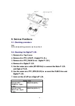
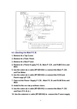
9.2. Checking the Digital P.C.B.
1. Remove the Top Cover.
2. Remove the FFC (ATAPI - Digital P.C.B.).
3. Remove the FFC (RAM Drive - Digital P.C.B.)
4. Remove the Digital P.C.B.
5. Use the extension cable (RFKZ0164) to connect the Main P.C.B.
and Digital P.C.B.
6. Use the extension FFC (RFKZ0125) to connect the RAM Drive and
Digital P.C.B.
7. Connect the ATAPI and Digital P.C.B.
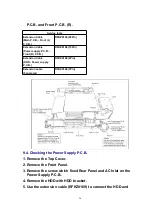
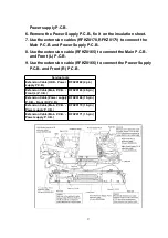
Service tools
Extension FFC
(RAM Drive - Digital
P.C.B.)
RFKZ0125 (40Pin)
Extension Cable
(Main P.C.B. - Digital
P.C.B.)
RFKZ0164 (30Pin x 3)
24
Summary of Contents for DMR-E80HPC
Page 12: ...6 2 3 Other Items needed Digital P C B HDD Conditions Nothing special 12 ...
Page 47: ...16 2 Casing Parts Mechanism Section 2 47 ...
Page 48: ...16 3 Packing Accessories Section 48 ...
Page 56: ...LB7402 03 J0JHC0000032 COIL 2 56 ...
Page 61: ...W501 08 ERJ3GEY0R00V 1 16W 0 8 61 ...
Page 63: ...C50028 ECJ1VF1C104Z 16V 0 1U 1 63 ...
Page 71: ...C122 KMG1E470 25V 47 1 71 ...
Page 148: ...1 A B C D 2 3 4 5 6 7 8 9 FRONT L P C B DMR E80H P PC FRONT L P C B REP3528DB ...
Page 149: ...1 A B C D 2 3 4 5 6 7 8 9 FRONT R P C B DMR E80H P PC FRONT R P C B REP3528EA ...
Page 158: ...5 6 7 8 Location Map DMR E80H P PC Main P C B REP3497M 2 4 Section 1 4 2 4 3 4 4 4 REAR FRONT ...
Page 160: ...Location Map DMR E80H P PC Main P C B REP3497M 4 4 Section 1 4 2 4 3 4 4 4 REAR FRONT ...
Page 176: ...1 A B C 2 3 4 5 6 7 8 9 ATAPI P C B DMR E80H P PC ATAPI P C B REP3542A ...


