


S-4
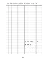
S3.2. AF LED/Mic Schematic Diagram / S3.3. CCD Flex Schematic Diagram
--#$#
2
&
$#&$
&
=$#&$?
.$
,,%%
,,%%
.$
4
.%<##
/
5'.(A.'&A-
/+%A)0&
/+%
5'.(A.'&A#
/+%A4')
61/#+0
&42#
6.1*
4
-
4
4
4
-
4
4
5%,.
3
3
5%,.
%
%
'%,8$%-
=?
(6
=/02/8?
+%
8#
8#
8.
8.
84
84
8
8
8
8
85
85
8
8
8$
8$
84
84
8#
8#
8
8
8.
8.
8$
8$
Ǟ8#
Ǟ8$
Ǟ8
)0&
)0&
Ǟ4
*.
*
*
%%&A)0&
%%&A)0&
%%&A)0&
%%&A)0&
%%&A)0&
%%&A)0&
4)
%%&176
57$59
57$59
8*
8#
84
8.
8$
8#
57$
57$
8.
84
8$
8
8
8.
8
85
8
8&&
8176
Ǟ85
0%
Ǟ8#
Ǟ8.
Ǟ8$
Ǟ8
Ǟ84
Ǟ8
Ǟ8
Ǟ84
Ǟ8.
8&&
Ǟ*.
26
Ǟ*#
Ǟ*#
Ǟ*$
Ǟ*$
DMC-FZ8
AF LED/Mic
Schematic Diagram
DMC-FZ8
CCD Flex
Schematic Diagram
10
9
8
7
6
5
4
3
2
1
G
F
E
D
C
B
A
Summary of Contents for DMC-FZ8EB
Page 12: ...12 4 Specifications ...
Page 13: ...13 5 Location of Controls and Components ...
Page 14: ...14 ...
Page 22: ...22 8 Disassembly and Assembly Instructions 8 1 Disassembly Flow Chart 8 2 PCB Location ...
Page 24: ...24 Fig D2 8 3 2 Removal of the Main P C B Unit Battery Frame Unit and Capacitor Holder Fig D3 ...
Page 28: ...28 8 4 3 Removal of the Master Flange Unit 8 4 4 Removal of the Cam Frame ...
Page 29: ...29 8 4 5 Removal of the Focus Motor Unit 8 4 6 Removal of the 4th Lens Frame Unit ...
Page 30: ...30 8 4 7 Removal of the 3rd Lens Frame Unit 8 4 8 Removal of the 2nd Lens Frame Unit ...
Page 41: ...S 8 ...


