


EN-4
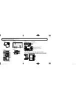
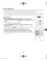
1. Receiver
Receives the signal sent from the remote
control.
2.
Emergency operation button
Display lamps
When an error occurs, one of the lamps fl ashes. When a
display lamp is blinking, refer to “14. Before Requesting
Service”.
3. Operating
lamp
This lamp is lit when the unit is operating.
4. Timer
lamp
This lamp is lit when the timer is set.
5. Standby
lamp
• When the heater is working, the lamp lights
at the following times. When the thermostat
has operated during defrosting at the time
of the startup.
• The lamp fl ashes when an error occurs.
6. Filter
lamp
This lamp is for notifying you when the fi lter
needs to be cleaned.
7. Swing
button
8.
Normal/Stop All switch
Use in the
Normal
position. It does not
operate in the
Stop All
position.
Remote control, main / remote control,
secondary, switch
In normal use this should be on remote
control, main. It is also possible to use both
in conjunction with a wired remote control
(sold separately). (Consult with the dealer
where the product was purchased about
making the settings.)
Test/On switch
This is used during service. It is not for
normal use.
Test Run/On switch
This is used during service. It is not for
normal use.
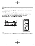
9. Address switch
Differentiate between incoming and outgoing
signals.
Note
• If a heat pump model is being used, it will beep
twice and the operating lamp will light up on the
display; if the timer and standby lamps blink
alternately, a confl ict between the heating and
cooling exists, so the unit cannot operate in the
desired mode. (On models that do not have an
Auto function, even if Auto is selected, it works in
the same way.)
• When the local operation is disabled by such as
the centralized control, and if the Start, Stop, Mode
or Temperature setting buttons are pressed, the
unit will beep fi ve times and the change will not be
made.
Receiver
2. Names and Operations (Cont.)
Instruction̲honbun̲all.indb EN-4
Instruction̲honbun̲all.indb EN-4
2012/09/12 12:39:12
2012/09/12 12:39:12


