Optional Controller
Manual of Controller
Optional Controller
Manual of Controller
2
- 45
2. Wireless Remote Controller
( CZ-RWSU2N, CZ-RWSD2, CZ-RWST3N, CZ-RWSL2N )
13
Common to All Models
ENGLISH
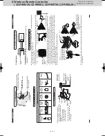
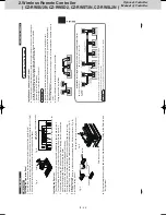
5-1.
Wiring f
or the R
eceiv
er
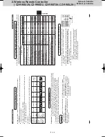
Installation L
ocation f
or the R
eciv
er
The wir
eless r
emote contr
ollers use a v
er
y w
eak infr
ar
ed light f
or its signal, which can r
esult in the signal
not being r
eceiv
ed because of the f
ollo
wing influences
, so tak
e car
e in wher
e the unit is instal
led.
•
Inv
er
ter or r
apid-star
t type fluor
escent lights (Models without glo
w lamps)
•
Plasma displa
y or L
CD tele
visions
•
Dir
ect sunlight or other sour
ces of bright light
Attention
Multiple wir
eless r
emote contr
ollers cannot be used simultaneously f
or a single indoor unit.
Be car
eful not to connect cables to other terminals of indoor units (e
.g.
po
wer sour
ce wiring terminal).
Malfunction ma
y occur
.
Do not bundle together with the po
wer sour
ce wiring or stor
e in the same metal tube
. Oper
ation err
or ma
y
occur
.
If noise is induced to the unit po
wer supply
, attach a noise filter
.
Installation when setting Main/Sub f
or the r
emote contr
oller and the r
eceiv
er
After installation, accor
ding to the
“Settings”
section, set one to [Main] and the other to [Sub].
Setting the wir
ed r
emote contr
oller to [Main] is r
ecommended.
The r
emote contr
oller and the r
eceiv
er can be connected to an
y indoor unit f
or oper
ation.
Note
12
12
R1
R2
R1
R2
R1
R2
R1
R2
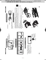
RC wiring (field supply) •
No polarity
Indoor unit
Indoor unit
Indoor unit
Indoor unit
12
12
R1
R2
Terminals f
or
RC wiring
Receiv
er (Sub)
Receiv
er (Sub)
Wir
ed R
C (Main)
Wired RC (Main)
Indoor unit
Using 1 indoor unit
Using mor
e than 1 indoor unit
RC wiring
(field supply) •
No polarity
Installation
ex
ample
R1
R2
R1
R2
R1
R2
12
12
12
Wir
ed R
C
Receiv
er
Indoor unit
Indoor unit
Indoor unit
RC wiring
Receiv
er
*Wiring sho
wn belo
w is pr
ohibited.
270059_all.indb 13
2015-1-20 9:53:48
12
CZ-R
W
SL2N
Metal P
anel
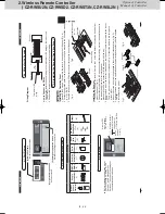
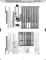
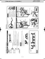
Installing the Oper
ation P
anel
1
Remo
ve the 2 scr
ew
s and r
emo
ve the co
ver A fr
om the back of the panel.
(Fig.
A)
2
Fasten the oper
ation panel to the location sho
wn in the figur
e belo
w with the 2 supplied scr
ew
s (4 × 10).
(Fig.
B)
3
Pass the r
eceiv
er wiring (6P white connector) thr
ough the back of the panel.
Installing the R
eceiv
er
1
The
co
ver B is fit in the Co
ver A.
Spr
ead the points as indicated in figur
e C and r
emo
ve it.
The tape holding co
ver B is only to pr
otect it during tr
anspor
t. R
emo
ve and discar
d it.
2
Connect the r
eceiv
er wiring (6P white connector) that is sticking out fr
om the oper
ation
panel to the r
eceiv
er and fit the r
eceiv
er into the panel.
Mak
e sur
e the 6P white connector is fully plugged in all the w
ay
.
3
Pass the lead wir
e f
or the r
eceiv
er thr
ough the cutout in the panel and the hole in the
metal panel.
Then f
asten it to the hole in the metal panel with the plastic clampe
r. (Fig.
D)
4
Attach the co
ver A.
5
Pr
operly r
oute the lead wir
e of the oper
ation panel and f
asten it with the twist lock.
(Fig.
B)
6
Install the ceiling panel.
F
or mor
e inf
ormation about wiring and test runs
, see the sections on
“Wiring f
or the R
eceiv
er”
and
“T
est Oper
ation”
.
Fig.
A
Co
ver A
Fig.
B
Loop e
xtr
a wiring and f
asten with
a twist lock.
Oper
ation panel
Supplied scr
ew
s (4 × 10)
Fig.
C
Co
ver B
Connect
Spr
ead
Receiv
er
Fasten the lead wir
e to hole in metal panel
Pass thr
ough cutout
Fig.
D
270059_all.indb 12
2015-1-20 9:53:47
SM830241-00_2WAY SYS.indb 45
2015/03/26 14:55:21
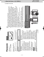
Summary of Contents for CZ-CSRC3
Page 18: ... MEMO 1 16 ...
Page 68: ...201504 ...


