background image

- 23 -

Service Adjustments (Electronic Controls, cont.)

20. In the Service Mode for making electronic

adjustments select the DAC DRIVE adjustments
(C3) RED, (C4) BLUE and adjust for warm white in
a white color bar pattern.

21. EXIT the Service Mode.
22. Adjust the Picture Menu Video Adjustments Bright

and Picture from low scale to high scale and check
Black and White tracking.

23. If correction is needed: Re-Enter the Service Mode

and perform the Minor Touch – Up Method.

24. Perform  Sub-Brightness Adjustment procedure if

needed.

Horizontal Centering

Service DAC Adjustment (C9)
Preparation:

Connect a monoscope pattern.

Procedure:
1.

In the Service Mode for making electronic
adjustments. Select the Horizontal Centering
Adjustment DAC (C9) and adjust until the center of
the crosshatch pattern is centered on CRT.

2.

EXIT the Service Adjustment Mode.

Audio Adjustment

Service DAC Adjustment (B6)
This adjustment is factory set and needs to be
performed only when IC002 or IC101 is replaced.

Preparation:
1.

Apply the following signal at the antenna (70dB
±5dB, 75

 open P/S 10dB): audio signal set to

monaural, 300Hz. 100% modulation; video input of
100 IRE flat field, 30% modulation.

2.

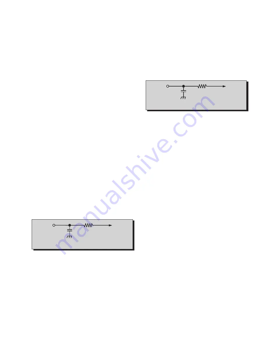
Connect the RMS Meter with filter jig as shown in
Fig. 24.

Procedure:
1.

In the Service Mode for making electronic
adjustments, select the Audio Adjustment DAC
(B6) and adjust until 75mV RMS ±5.0mV RMS is
measured.

2.

EXIT the Service Adjustment Mode.

MTS Circuit Adjustments

The MTS Circuit Adjustments require two steps:
1.

Input Level Adjustment.

2.

Stereo Separation Adjustment.

Input Level Adjustment (M0)

Preparation:
1.

Connect an RMS meter with filter jig as shown in
Fig. 25.

2.

Connect an RF signal generator to the RF
antenna input.

Procedure:
1.

Apply the following signal from the RF signal
generator:
Video: 100 IRE flat field, 30% modulation.
Audio: 300Hz, 100% modulation, monaural
(70 ±5dB, 75

 OPEN, P/S 10dB).

2.

Adjust the MTS Input Level Adjustment (M0) until
the voltage measured is 106 ± 6.0mV rms.

Stereo Separation Adjustment (M1 & M2)

Preparation:
1.  Connect an RF signal generator to the RF antenna

input.

2.

Connect a scope to TPE10.

Procedure:
1.

Select Stereo Mode in Audio menu

2.

Apply the following signal from the RF signal
generator:
Video: 100 IRE flat field, 30% modulation.
Audio: 300Hz, 100% modulation, stereo (left only)
(70 ±5dB, 75

 OPEN, P/S 10dB).

3.

Adjust the MTS Low-Level Separation Adjustment
(M2) until the amplitude displayed on the scope
is minimum.

4.

Apply the following signal from the RF
signal generator:

Video: 100 IRE flat field, 30% modulation.
Audio: 3KHz, 100% modulation, stereo (left only)

(70 ±5dB, 75

 OPEN, P/S 10dB).

5.

Adjust the MTS High-Level Separation Adjustment
(M1) until the amplitude displayed on the scope is
minimum

6.

.Repeat above steps 2 through 5 until the
amplitude is at minimum for both signals.Service
Adjustments (Electronic Controls, cont.)

10k

4700p

Figure 24.  Filter Jig

TPE1

RMS

(A-BOARD)

METER

10k

4700p

TPE10

RMS

METER

Figure 25.  Filter Jig

Summary of Contents for CT20SX11E - 20" COLOR TV

Page 1: ...or cautions to advise non technical individuals of potential dangers in attempting to service a product Products powered by electricity should be serviced or repaired only by experienced professional technicians Any attempt to service or repair the product or products dealt with in this Service Manual by anyone else could result in serious injury or death Chassis CT 20SX11E AP380 CT 20SX11CE AP380...

Page 2: ...glass provide shielding for the tube viewing area against X ray radiation as well as implosion The magnetic shield limits the X ray radiation around the bell of the picture tube in addition to the restricting magnetic effects When using a picture tube test jig for service ensure that the jig is capable of handling 40kV without causing X ray radiation Before returning a serviced receiver to the own...

Page 3: ...ty 18 Helpful Hints 18 Instructional Flow Chart for Service Mode 19 Service Adjustments Electronic Control 21 Sub Brightness 21 Video Adjustment Level 21 Sub Contrast 21 Tint Color Adjustment 21 Color Temperature Adjustment 22 Complete Adjustment 22 Horizontal Centering 23 Audio Adjustment 23 MTS Circuit Adjustment 23 Input Level Adjustment 23 Stereo Separation Adjustment Sb 23 Clock Adjustment Sb...

Page 4: ...g pads with tweezers or with a miniature alligator clip and apply heat to the pad area with a 30 watt iron until solder flows Do not apply heat for more than 3 seconds How to Replace Flat IC Required Tools 1 Cut the pins of a defective IC with wire cutters Remove IC from board If IC is glued to the board heat the IC and release the IC See Note above 2 Using soldering iron and needle nose pliers re...

Page 5: ...orrect voltages will be measured WARNING This Receiver has been designed to meet or exceed applicable safety and X ray radiation protection as specified by government agencies and independent testing laboratories To maintain original product safety design standards relative to X ray radiation and shock and fire hazard parts indicated with the symbol on the schematic must be replaced with identical...

Page 6: ... Surround Sound X AI Sound X FAO VAO X Built in audio power 5Wx2 10 of speakers 2 A V in rear front 2 2 1 S VHS Input rear front 1 0 Headphone Jack X Dimensions mm WxDxH in 550x479x491 5 21 7 x 18 9 x 19 4 Weight kg lbs 24 5 54 13 Power source V Hz 120 60 Anode voltage 27 7kV 1 25kV Video input jack 1Vp p 75Ω phono jack Audio input jack 500mV RMS 47kΩ A Board TNP2AH019 KA C Board TNP2AA047 AY Z Bo...

Page 7: ...el Buttons Press to select programmed channels Press to highlight desired features when menus are displayed Also use to select Cable Converter box channels after programming Remote Control Infra red codes the TV AUX CABLE switch must be set in CABLE position Action Button Press to display Main Menu and access On Screen feature and Adjustment Menus TV Video Button Press to select TV or Video Input ...

Page 8: ...ion Station Identifier 0 9 Press numeric keypad to select any channel Power Button Press to turn ON and OFF ACTION Button Press to display Main Menu and access or exit On Screen features and Adjustment Menus TV VCR DBS CBL DVD Component function buttons VOL volume Buttons Press to adjust TV sound level Use with Channel buttons to navigate in menus Mute Button Press to mute sound A second press res...

Page 9: ... base and unplug the black wire CRT dag ground C10 4 Disconnect the A11 A12 and Speakers plugs from the A Board 5 Lift the Main Chassis A Board and all mounted boards completely out with the CRT Board attached CRT Replacement 1 Perform Disassembly for CRT Replacement procedure 2 Insure that the CRT H V Anode button is discharged before handling the CRT Read the Safety Precautions see page 2 on han...

Page 10: ...is voltage supplies B to the Horizontal Output Flyback circuits Source Voltage Chart 120V AC line input Set the Bright and the Picture to Minimum by using the Picture Menu Use cold ground for the lead of the DVM Adjust Picture Menu for normalized video adjustments High Voltage Check 1 Select an active TV channel and confirm that horizontal is in sync 2 Adjust Brightness and Picture using Picture I...

Page 11: ...lection yoke back and forth on the neck of the CRT until it produces a near white uniform raster Vertical Raster Shift Adjustment Only for Models with Purity Convergence Assembly with 4 Pairs of Rings Apply a green pattern with a horizontal line adjust the Deflection Yoke so that has no tilt then secure it Adjust center line of the pattern with the mechanical center of the CRT this center is deter...

Page 12: ...gain until Purity check white screen appears Observe the screen for uniform white If purity has not been achieved repeat the above procedure Final Convergence Procedure see Fig 11 through Fig 13 Note Vertical size and focus adjustments must be completed prior to performing the convergence adjustment Connect a dot pattern generator to the Receiver The Brightness level should not be higher than nece...

Page 13: ...s the yoke is tilted horizontally one raster gets larger while the other gets smaller Figure 12 Horizontal Yoke Movement 11 o clock Position Double sided adhesive tape 3 o clock Position 7 o clock Position Converges R B with G Converges R with B Purity Convergence Assembly Clamp Purity Rings Adj on Green Raster Static Convergence Magnets Yoke Positioning Wedges for Dynamic Convergence Figure 13 Co...

Page 14: ...he VOL button decrease on Receiver Red CHK appears in upper corner 7 Press the Power Button on the Remote Control to select one of six Service Adjustment Modes 1 B Service VCJ SUB DATA ADJUSTEMENT 2 C Service VCJ CUT OFF ADJUSTMENT 3 S Service OPTIONS PIP and CLOCK ADJUSTMENT 4 M Service MTS ADJUSTMENTS 5 X Service COMB FILTER ADJUSTMENT 6 CHK Normal operation of CHANNEL and VOLUME Exiting the Ser...

Page 15: ...ge Default Level C0 CUT OFF R 0 1 0 255 0 193 C1 CUT OFF G 0 255 92 C2 CUT OFF B 0 1 0 255 0 186 C3 DRIVE R 0 127 57 C4 DRIVE B 0 127 57 C5 YNR SWITCH 0 1 0 C6 AFT 0 1 0 225 1 126 C7 RF AGC 0 127 63 C8 YNR VIDEO ADJUSTMENT 0 7 0 C9 HORIZONTAL CENTER 0 31 12 Ca BEAM LIMIT 0 7 4 Cb VCJ TEST H 0 2 0 1 Press Channel Up Down on the Remote Control to select one of the available Service Adjustments a in ...

Page 16: ... 63 58 Sd LOUDNESS COMPENSATION 0 63 52 MTS Adjustment Adj Range Default Level M0 INPUT LEVEL 0 63 30 M1 HIGH LEVEL SEPARATION 0 63 26 M2 LOW LEVEL SEPARATION 0 15 11 1 Press Channel Up Down on the Remote Control to select one of the available Service Adjustments a in Fig 14 Note Write Down the original value set b in Fig 14 for each address before modifying anything It is easy to erroneously adju...

Page 17: ...COMB VMPKF 0 1 1 Xb COMB ADJ SHARP 0 63 10 1 Press Channel Up Down on the Remote Control to select one of the available Service Adjustments a in Fig 14 Note Write Down the original value set b in Fig 14 for each address before modifying anything It is easy to erroneously adjust the wrong item 2 Press Volume Up Down on the Remote Control to adjust the level of the selected Service Adjustment b in F...

Page 18: ...ceiver is ON and operating in Normal Mode momentarily short test point FA1 TP8 to Cold Ground FA2 TP3 A Board The Receiver enters the Aging Mode Yellow letters CHK appear in the upper left corner of the CRT The Volume Up Down will adjust rapidly 2 Simultaneously press the Action and the Volume Up buttons on the Receiver Control Panel The Receiver enters the Service Mode The letter in CHK turn red ...

Page 19: ...EMOTE AGING MODE Yellow CHK appears in upper left corner of screen Volume Up Down operate rapidly Customer Controls are set to nominal level SERVICE MODE CHK turns red Volume Up Down operate normally Customer Controls are set to nominal level SUB DATA ADJUSTMENTS B ITEMS A QUICK ENTRY TO SERVICE MODE Select CABLE Mode Set SLEEP time for 30 Min Tune to Channel 124 Adjust Volume to minimum Press VOL...

Page 20: ...needed B Y N N ON REMOTE CH ON REMOTE CH ON REMOTE CH ON REMOTE CH POWER ON REMOTE ON REMOTE CH POWER ON REMOTE POWER ON REMOTE POWER ON REMOTE ON REMOTE CH Sd LOUDNESS COMPENSATION Sc PIP TINT Sb CLOCK ADJUSTMENT Sa FREERUN S9 RIGHT 1 16 S8 LEFT 1 16 S7 DOWN 1 16 S6 UP 1 16 S5 RIGHT 1 9 S4 LEFT 1 9 S3 DOWN 1 9 S2 UP 1 9 S1 PIP CONTRAST S0 PIP COLOR M2 LOW LEVEL SEPARATION M1 HIGH LEVEL SEPARATION...

Page 21: ...ment B3 Sub Contrast Service DAC Adjustment B3 This adjustment is factory set Do not adjust unless repairs are made to associated circuit the CRT Board or when the CRT is replaced Preparation 1 Apply a color bar signal pattern with 87 5 modulation 70 saturated color bar with a 100 IRE white and 7 5 black Note The pattern used in this procedure is an EIA color bar pattern with 87 5 modulation with ...

Page 22: ... Horizontal rate and adjust the Service Mode Sub Bright DAC B2 level until a scanning period of 3 1V above DC ground is measured as indicated in Fig 22 5 Connect the scope to GRN Cathode KG on the CRT Board 6 In the Service Mode for making electronic adjustments select the GREEN CUTOFF DAC C1 7 Press the R Tune key on the remote 8 View scope trace at Horizontal rate and adjust the Service Mode DAC...

Page 23: ...MS is measured 2 EXIT the Service Adjustment Mode MTS Circuit Adjustments The MTS Circuit Adjustments require two steps 1 Input Level Adjustment 2 Stereo Separation Adjustment Input Level Adjustment M0 Preparation 1 Connect an RMS meter with filter jig as shown in Fig 25 2 Connect an RF signal generator to the RF antenna input Procedure 1 Apply the following signal from the RF signal generator Vid...

Page 24: ...Best results can de obtained with a round test patter Service Adjustments Mechanical Controls VCO Field Alignment L105 IC101 pins 35 36 1 Connect a balance antenna and select a midband channel Ch 10 11 or 12 2 Attenuate the signal strength for a weak noisy video 3 While observing the picture tube adjust L105 until best picture appears 4 Change channels and observe that they are tuning properly 5 I...

Page 25: ... 25 Audio Signal Path Block Diagram Figure 26 Audio Signal Path Block Diagram ...

Page 26: ... 26 Video Chroma Signal Path Block Diagram Figure 27 Video Chroma Path Block Diagram ...

Page 27: ... Components Figure 28 Back Cover Removal 2 screws at the top edge of the receiver 1 screw by the A V jacks 1 screw by the flyback assembly 1 screw at the lower edge of the receiver 1 screw at the lower edge of the receiver ...

Page 28: ... View CRT secured to cabinet by 4 screws on corners of CRT Anode high voltage C board Tuner A V jacks Flyback T551 Note After servicing the receiver remember to dress the cables as shown Yoke Speaker 4 screws Degaussing coil Speaker Bracket 2 screws ...

Page 29: ... of Components Figure 30 A Board Main Components IC6501 COMB FILTER IC002 EEPROM IC101 VCJ IC001 MPU TNR001 TUNER IC451 V OUT KEYPAD Q551 H OUT T551 FBT F801 FUSE IC003 SENSOR IC2321 AUDIO IC2302 AUDIO AMP IC803 POWER S ...

Page 30: ... 30 Identification of Components Figure 31 Component Identification C Z Boards CRT SOCKET Q353 Q352 Q351 R760 R761 Q751 Q753 C BOARD Z BOARD Q752 ...

Page 31: ...A1VM102E CAP E 1000UF 35V C2302 ECA1HM010B CAP E 1UF 50V C2305 ECA1HM010B CAP E 1UF 50V C2306 TCJ2VF1H103Z CAP C 01UF Z 50V C2307 ECA1CM102B CAP E 1000UF 16V C2309 ECQB1H473JM3 CAP P 047UF J 50V C2311 ECA1HM2R2B CAP E 2 2UF 50V REF NO PART NO DESCRIPTION C2313 ECA1EM101B CAP E 100UF 25V C2314 ECQB1H473JM3 CAP P 047UF J 50V C2315 ECA1EM100B CAP E 10UF 25V C2321 ECA1EM100B CAP E 10UF 25V C2324 ECA1E...

Page 32: ...IODE D560 MA165TA5VT DIODE SWITCHING D561 BYD33G 163 DIODE D751 MA2270B DIODE D801 GP15KL 042 DIODE D802 GP15KL 042 DIODE D806 MA4056MTA DIODE D807 MA165TA5VT DIODE SWITCHING D809 RU3YX MV1 DIODE RECTIFIER D810 TAP2A102M005 DIODE THERMISTOR D820 EU02V1 DIODE REF NO PART NO DESCRIPTION D821 EU02V1 DIODE D822 EU02V1 DIODE D823 RL30A DIODE D824 EU02V1 DIODE D825 TVSSR2KLV1 DIODE PROTECTION D826 EU02V...

Page 33: ...TRANSISTOR Q551 2SD2499LBMA2 TRANSISTOR Q751 2SC1685QRSTA TRANSISTOR Q752 2SA564AQRSTA TRANSISTOR Q753 2SD1266PLB TRANSISTOR REF NO PART NO DESCRIPTION Q801 2SC1685RSTA TRANSISTOR Q802 2SC1384RS TRANSISTOR Q2302 2SB709ARTX TRANSISTOR Q2303 2SD601ARTX TRANSISTOR Q2362 2SB709ARTX TRANSISTOR Q2363 2SD601ARTX TRANSISTOR Q2409 2SD601ARTX TRANSISTOR Q2410 2SD601ARTX TRANSISTOR Q6501 2SD601ARTX TRANSISTO...

Page 34: ...102V RES M 1K J 1 10W R351 ERG2FJ123H RES M 12K J 2W R352 ERG2FJ123H RES M 12K J 2W R353 ERG2FJ123H RES M 12K J 2W R354 ERDS1TJ272T RES C 2 7K J 1 2W R355 ERDS1TJ272T RES C 2 7K J 1 2W R356 ERDS1TJ272T RES C 2 7K J 1 2W REF NO PART NO DESCRIPTION R357 ERDS2TJ331T RES C 330 J 1 4W R358 ERDS2TJ331T RES C 330 J 1 4W R359 ERDS2TJ331T RES C 330 J 1 4W R360 ERDS2TJ122T RES C 1 2K J 1 4W R361 ERDS2TJ122T...

Page 35: ... 2W R827 ERDS1FJ561P RES C 560 J 1 2W R828 ERG3FJ470 RES M 47 J 3W R829 ERQ14AJ270P RES F 27 J 1 4W R2201 ERJ6GEYJ224V RES M 220K J 1 10W REF NO PART NO DESCRIPTION R2206 ERJ6GEYJ102V RES M 1K J 1 10W R2207 ERJ6GEYJ102V RES M 1K J 1 10W R2220 ERJ6GEYJ101V RES M 100 J 1 10W R2301 ERQ2CJP1R0S RES F 1 0 J 2W R2305 ERD25FJ180T RES C 18 J 1 4 R2306 ERD25FJ180T RES C 18 J 1 4 R2307 ERJ6GEYJ221V RES M 22...

Page 36: ...RES M 12K J 1 10W R6558 ERJ6GEYJ331V RES M 330 J 1 10W R6559 ERJ6GEYJ272V RES M 2 7K J 1 10W R6560 ERJ6GEYJ124V RES M 120K J 1 10W R6565 ERJ6GEYJ102V RES M 1K J 1 10W R6566 ERJ6GEYJ681V RES M 680 J 1 10W R6567 ERJ6GEYJ222V RES M 2 2K J 1 10W R6568 ERJ6GEYJ471V RES M 470 J 1 10W R6571 ERJ6GEYJ472V RES M 4 7K J 1 10W SWITCHES S001 TSE2AD001 SWITCH PUSH S002 TSE2AD001 SWITCH PUSH S003 TSE2AD001 SWITC...

Page 37: ...s B 7 Los diagramas eléctricos están sujetos a cambio sin previo aviso 8 El símbolo indica que es una conexión a Tierra Caliente y el símbolo indica conexión a Tierra Fría NOTA Los demas símbolos de componentes incluidos son usados con fines de diseño Schematic Notes 1 Resistors are carbon 1 4W unless noted otherwise 2 Capacitors are ceramic 50V unless noted otherwise 3 Coil value notes is inducta...

Page 38: ... 39 ALL MODELS A BOARD SCHEMATIC LEFT PORTION DIAGRAMA ELECTRICO DE LA TARJETA A SECCION IZQUIERDA ...

Page 39: ...ES IMPORTANTE USAR PARA REEMPLAZO DE COMPONENTES CRITICOS SOLO PARTES ESPECIFICADAS POR EL FABRICANTES LOS COMPONENTES CRITICOS ESTAN SEÑALADOS EN LOS DIAGRAMAS POR EL SIMBOLO IMPORTANT SAFETY NOTICE THIS SCHEMATIC DIAGRAM INCORPORATES SPECIAL FEATURES THAT ARE IMPORTANT FOR PROTECTION FROM X RADIATION FIRE AND ELECTRICAL SHOCK HAZARDS WHEN SERVICING IT IS ESSENTIAL THAT ONLY MANUFACTURERS SPECIFI...

Page 40: ... 41 ALL MODELS A BOARD LAYOUT DIAGRAMA IMPRESO DE LA TARJETA A ...

Page 41: ...9 10 11 12 13 14 15 16 17 18 19 20 21 22 23 24 25 26 27 28 0 00 4 96 0 00 0 00 0 00 0 00 0 00 4 95 3 18 3 15 0 00 2 41 0 00 2 32 2 47 3 46 3 46 2 35 0 00 2 46 1 47 0 50 4 95 0 38 1 14 1 13 3 58 0 57 IC6502 1 2 3 4 5 0 00 0 00 0 00 4 95 4 93 IC801 1 2 3 4 0 59 0 00 12 27 0 00 IC803 1 2 3 4 5 90 12 132 14 249 21 131 90 133 2 IC804 1 2 3 4 13 50 0 00 6 40 6 27 Q001 0 75 0 00 0 00 B C E Q002 5 86 10 1...

Page 42: ...CHEMATIC DIAGRAM INCORPORATES SPECIAL FEATURES THAT ARE IMPORTANT FOR PROTECTION FROM X RADIATION FIRE AND ELECTRICAL SHOCK HAZARDS WHEN SERVICING IT IS ESSENTIAL THAT ONLY MANUFACTURERS SPECIFIED PARTS BE USED FOR THE CRITICAL COMPONENTS DESIGNATED WITH A IN THE SCHEMATIC NOTA DE SEGURIDAD LOS DIAGRAMAS ELÉCTRICOS INCLUYEN CARACTERÍSTICAS ESPECIALES MUY IMPORTANTES PARA LA PROTECCIÓN CONTRA RAYOS...

Page 43: ...egro 3 Los ajustes de usuario de los Menus PICTURE y AUDIO se normalizaron Posteriormente el nivel de volumen se ajusta al mínimo 4 Las formas de onda de Video y Color fueron tomadas con un osciloscopio de banda alta y con un punta de prueba de baja capacitancia 10 a 1 La forma y amplitud de las ondas puede variar según el tipo de osciloscopio que se utilice y sus características 5 El símbolo de t...

Page 44: ... 45 ...

Page 45: ...CAP P 068UF K 50V RESISTOR TYPE TOLERANCE C Carbon F 1 F Fuse J 5 M Metal Oxide K 10 S Solid M 20 W Wire Wound G 2 CAPACITOR TYPE TOLERANCE C Ceramic C 0 25pF E Electrolytic D 0 5pF P Polyester F 1pF S Styrol J 5 T Tantalum K 10 L 15 M 20 P 10 0 Z 80 20 ...

Page 46: ... 47 Printed in USA K01072593CM0718 ...

Reviews: