46
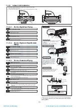
11.3.5 Piping
Insulation
1 Please carry out insulation at pipe connection portion as mentioned in Indoor/Outdoor Unit Installation
Diagram. Please wrap the insulated piping end to prevent water from going inside the piping.
2 If drain hose or connecting piping is in the room (where dew may form), please increase the insulation by
using POLY-E FOAM with thickness 6 mm or above.
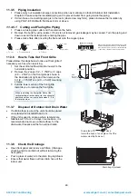
11.3.5.1 Cutting
and
Flaring the Piping
1 Please cut using pipe cutter and then remove the burrs.
2 Remove the burrs by using reamer. If burrs is not removed, gas leakage may be caused. Turn the piping end
down to avoid the metal powder entering the pipe.
3 Please make flare after inserting the flare nut onto the copper pipes.
11.3.6 How
to
Take
Out Front Grille
Please follow the steps below to take out front grille if
necessary such as when servicing.
1 Set the vertical airflow direction louvers to the
horizontal position.
2 Remove the 2 caps (1/2 ~ 1.75HP) or 3 caps
(2.0 ~ 2.5HP) on the front grille as shown in
the illustration at right, and then remove the
3 (1/2 ~ 1.75HP) or 4 (2.0 ~ 2.5HP) mounting
screws.
3 Pull the lower section of the front grille
towards you to remove the front grille.
When reinstalling the front grille, first set the
vertical airflow direction louver to the horizontal
position and then carry out above steps 2 - 3 in
the reverse order.
11.3.7 Disposal of Outdoor Unit Drain Water
If a drain elbow is used, the unit should be placed
on a stand which is taller than 3 cm.
If the unit is used in an area where temperature
falls below 0°C for 2 or 3 days in succession, it is
recommended not to use a drain elbow, for the
drain water freezes and the fan will not rotate.
11.3.8 Check the Drainage
Open front panel and remove air filters. (Drainage
checking can be carried out without removing the
front grille.)
Pour a glass of water into the drain tray-styrofoam.
Ensure that water flows out from drain hose of the
indoor unit.
When properly fl ared, the internal surface of the
fl are will evenly shine and be of even thickness.
Since the fl are part comes into contact with the
connections, carefully check the fl are fi nish.
Improper fl aring
Inclined Surface
damaged
Cracked Uneven
thickness
1. To cut
2. To remove burrs
3. To fl are
Bar
Red arrow mark
Handle
Core
Yoke
Clamp handle
Bar
0 – 0.5 mm
Copper pipe
Reamer
Point down
Pipe
Screw
Screw
Vane
Cap
Test pen
Move
the vane
downward
• Use Test pen to
remove Cap
(only for 2.0HP ~ 2.5HP
model)
Front grille
Front grille
Hose
Install the hose at an angle so that the
water smoothly fl ows out.
Drain elbow
7
Drain tray-styrofoam
AMP Air Conditioning
www.ampair.co.uk | [email protected]


