


32
1. Connect a charging hose with a push pin to the Low side of a charging set and the service port of the 3-way valve.
• Be sure to connect the end of the charging hose with the push pin to the service port.
2. Connect the center hose of the charging set to a vacuum pump.
3. Turn on the power switch of the vacuum pump and make sure that the needle in the gauge moves from 0 cmHg (0 MPa) to
-76 cmHg (-0.1 MPa). Then evacuate the air approximately ten minutes.
4. Close the Low side valve of the charging set and turn off the vacuum pump. Make sure that the needle in the gauge does not
move after approximately five minutes.
Note : BE SURE TO TAKE THIS PROCEDURE IN ORDER TO AVOID REFRIGERANT GAS LEAKAGE.
5. Disconnect the charging hose from the vacuum pump and from the service port of the 3-way valve.
6. Tighten the service port caps of the 3-way valve at a torque of 18 N•m with a torque wrench.
7. Remove the valve caps of both of the 2-way valve and 3-way valve. Position both of the valves to “OPEN” using a hexagonal
wrench (4 mm).
8. Mount valve caps onto the 2-way valve and the 3-way valve.
• Be sure to check for gas leakage.
11.3.4.
Air Purging Of The Piping And Indoor
The remaining air in the Refrigeration cycle which contains moisture may cause malfunction on the compressor.
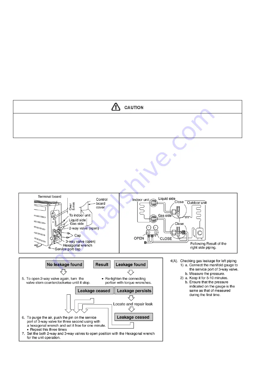
1. Remove the caps from the 2-way and 3-way valves.
2. Remove the service-port cap from the 3-way valves.
3. To open the valve, turn the valve stem of 2-way valve counter-clockwise approx. 90
°
and hold it there for ten seconds, then
close it.
4. Check gas-leakage of the connecting portion of the pipings.
• For the left pipings, refer to item 4(A).
• If gauge needle does not move from 0 cmHg (0 MPa) to -76 cmHg (-0.1 MPa), in step
3
above take the following measure:
- If the leak stops when the piping connections are tightened further, continue working from step
3
.
- If the leak does not stop when the connections are retightened, repair location of leak.
- Do not release refrigerant during piping work for installation and reinstallation.
- Take care of the liquid refrigerant, it may cause frostbite.
Summary of Contents for CS-PC12KKF
Page 10: ...10 4 Location of Controls and Components 4 1 Indoor Unit 4 2 Outdoor Unit 4 3 Remote Control ...
Page 11: ...11 5 Dimensions 5 1 Indoor Unit 5 1 1 CS PC12KKF ...
Page 12: ...12 5 1 2 CS PC18KKF CS PC24KKF ...
Page 13: ...13 5 2 Outdoor Unit 5 2 1 CU PC12KKF CU PC18KKF ...
Page 14: ...14 5 2 2 CU PC24KKF ...
Page 15: ...15 6 Refrigeration Cycle Diagram ...
Page 16: ...16 7 Block Diagram 7 1 CS PC12KKF ...
Page 17: ...17 7 2 CS PC18KKF CS PC24KKF ...
Page 21: ...21 9 Electronic Circuit Diagram 9 1 CS PC12KKF ...
Page 22: ...22 9 2 CS PC18KKF CS PC24KKF ...
Page 23: ...23 10 Printed Circuit Board 10 1 Indoor Unit 10 1 1 Main Printed Circuit Board ...
Page 24: ...24 10 1 2 Power Printed Circuit Board 10 1 2 1 CS PC12KKF 10 1 2 2 CS PC18KKF CS PC24KKF ...
Page 25: ...25 10 2 Indicator Printed Circuit Board ...
Page 49: ...49 16 1 1 3 To remove Discharge Grille ...
Page 50: ...50 16 1 1 4 To remove Control Board 16 1 1 5 To remove Cross Flow Fan and Indoor Fan Motor ...
Page 51: ...51 ...
Page 53: ...53 16 2 1 3 To remove Discharge Grille ...
Page 54: ...54 16 2 1 4 To remove Control Board 16 2 1 5 To remove Cross Flow Fan and Indoor Fan Motor ...
Page 55: ...55 ...
Page 56: ...56 17 Technical Data 17 1 Thermostat Characteristics Cooling Soft Dry ...
Page 57: ...57 17 2 Operation Characteristics 17 2 1 CS PC12KKF CU PC12KKF ...
Page 58: ...58 ...
Page 59: ...59 17 2 2 CS PC18KKF CU PC18KKF ...
Page 60: ...60 ...
Page 61: ...61 17 2 3 CS PC24KKF CU PC24KKF ...
Page 62: ...62 ...
Page 63: ...63 17 3 Fan Performance 17 4 Cooling Capacity Performance Data CS CU PC12KKF 220V ...
Page 64: ...64 CS CU PC12KKF 240V CS CU PC18KKF 220V ...
Page 65: ...65 CS CU PC18KKF 240V ...
Page 66: ...66 CS CU PC24KKF 220V ...
Page 67: ...67 CS CU PC24KKF 240V ...
Page 68: ...68 17 5 Sound Data CS PC18KKF ...
Page 69: ...69 CS PC24KKF ...


