background image

23

21

E
N

G

L

I

S
H

22

E
N

G

L

I

S
H

CQ-VA7300N

CQ-VA7300N

22

3

Setting

VOL

VOL

VOL

NAVI

NAVIGATION

ASP

ASPECT

TILT

MUTE

MUTE

MUTE

DISP

PTY

TA

AF

MONO/ST

ENTER

MODE

POWER

MENU

EON

PTY

CT

IN-DASH 7 INCH COLOR LCD MONITOR WITH RECEIVER

CQ-VA7300N

LOUD

TRACK
TUNE

PRESET / DISC

OPEN / CLOSE

CQ-VA7300N

ENTER

MODE

MENU

1

2

[ENTER]

[

}

] [

{

]  

[

]

] [

[

]

(Select/adjust) 

[MENU] 

[MODE]

(End) 

User Settings

Menu

Submenu

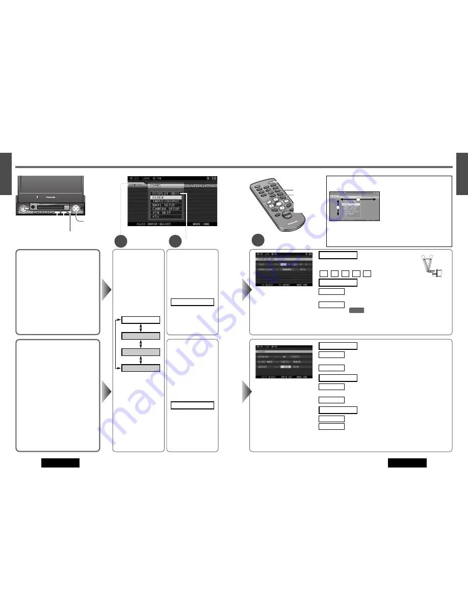
Display Unit

TILT (Tilting angle adjustment)

Default: 5
Setting range: 1 to 5

OPEN/CLOSE

Automatic monitor OPEN/CLOSE in accordance
with ACC ignition switch ON/OFF

Default: MANUAL

Notes: 

¡

For smooth adjustment, make sure to first return the lateral angle to the neutral position and then adjust the tilt angle.

¡

The monitor position setting menu can also be displayed by pressing the 

[TILT]

button on the display unit for more

than 1 second. (

a

page 11)

5

4

3

2

1

Tilting angle adjustment

Press 

[

]

]

or

[

[

]

to select the setting.

TILT

[

]

]

[

[

]

Monitor setup

: no interlock between monitor OPEN/CLOSE and ACC

ON/OFF 

: interlock between monitor OPEN/CLOSE and ACC ON/OFF

(

ACC ON

AUTO

MANUAL

OPEN/CLOSE

q

Press 

[

}

]

or 

[

{

]

to

select “DISPLAY UNIT”.

w

Press 

[ENTER]

to set.

DISPLAY UNIT

q

Press 

[

}

]

or 

[

{

]

to

select “CLOCK”.

w

Press 

[ENTER]

to set.

CLOCK

q

Press 

[MENU]

to

display the menu.

w

Press 

[

[

]

or 

[

]

]

to

select “USER”. 

RDS

SCREEN

SOUND

USER

*Make selection and adjustment.

*Make a selection.

Clock display for the monitor

: clock display ON ([0:00] is displayed before adjusting 

the clock.)

: clock display OFF

Clock preference

: The clock is automatically adjusted using the RDS clock time

service function. (

a

page 14)

: Manually adjusted time is displayed.

Adjusting the clock manually

: Press 

[

]

]

to adjust the hour.

: Press 

[

[

]

to adjust the minute.

00/M

0/H

ADJUST

MANUAL

RDS

CLOCK MODE

OFF

ON

DISPLAY

Notes: 

¡

To change numbers rapidly while adjusting cock, hold 

[

]

]

or 

[

[

]

.

¡

The clock starts by pressing 

[MODE]

or 

[MENU]

after clock adjustment.

Clock Setting

Default: DISPLAY...OFF

CLOCK MODE...RDS
ADJUST...0/H, 00/M

Notes: 

¡

The clock starts after the unit returns to the
regular mode by pressing 

[MODE]

.

¡

The 24-hour clock system is adopted.

¡

Press 

[MODE]

(End) to close the main menu and the setting/adjusting

menu.

¡

Press 

[MENU]

in the setting/adjusting menu to return to the main

menu mode.

2

1

q

[

}

and

[

{

]

buttons move the 

cursor vertically.

w

[

[

]

and 

[

]

]

buttons 

move the 

cursor horizontally.

e

To set, press 

[ENTER]

.

*Making selection and adjustment on the Menu. 

PW

R

MO

DE

CH 

1

1

4

TA

AF

LOC

ENT

ER

MU

TE

LOU

D

VOLU

ME

CA

R A

V

NA

VI

NAV

IGAT

ION

SCRO

LL

DISP

ASPECT

MENU

P·M

OD

E

PTY

5

6

2

3

RAN

DOM

SCA

N

REP

EAT

CH 

2

ENT

ER

MENU

[

}

] [

{

[

]

] [

[

]

(Select/adjust) 

[ENTER] 

[MODE] 

(End)

[MENU] 

Note: 

The menu RDS can

not be selected in the
modes other than FM
mode.

Summary of Contents for CQ-VA7300N

Page 1: ...ig auf Prière de lire ces instructions attentivement avant d utiliser le produit et garder ce manuel pour l utilisation ultérieure Leest u deze instructie alstublieft zorgvuldig door voor u dit product in gebruik neemt en bewaar deze handleiding voor later gebruik Läs igenom denna bruksanvisning noga innan produkten tas i bruk Spara bruksanvisningen för framtida behov Si prega di leggere attentame...

Page 2: ...Removable face plate This serviceable mechanism allows you to protect your valuable system from theft Fully powered display positioning mechanism Positioning of the display unit is fully power driven This includes extending the unit raising it to upright position adjusting its vertical tilt angle GUI Graphical User Interface GUI displays various indications with colorful symbols to enhance visibil...

Page 3: ...must not operate the color LCD liquid crystal display monitor Operating the color LCD monitor may lead to carelessness and cause an accident Stop your vehicle in a safe location when operating the unit The driver must not watch videos while driving It may lead to carelessness and cause an accident Keep the unit at an appropriate volume level Driving with the sound at a level that prevents you from...

Page 4: ...ge 10 MUTE LOUD Mutes the sound temporarily a page 10 Compensates bass and treble in the low and middle volume level LOUD a page 10 P MODE Private mode Activate inactivate the private mode a page 41 1 6 Memorizes and recalls broadcast stations a page 13 4 RANDOM 5 SCAN 6 REPEAT Random scan repeat play for CD Changer Video CD Changer mode a page 21 1 CH 1 2 CH 2 Switches changer 1 and 2 when two ch...

Page 5: ...O and MONO Press and hold a page 12 DISP PTY Changes display a page 38 Switches PTY mode on and off Press and hold a page 16 ENTER Selects a band a page 12 Searches for broadcast stations and memorizes them auto matically a page 13 Determines an operation or item PRESET DISC Selects vertically or adjusts an operation or item Selects a disc a page 21 Selects a preset station a page 13 TRACK TUNE Se...

Page 6: ...LOSE again and draw it all the way in Opening closing the display can also be done when the power is off ACC ON Power Turn your car s ignition key to ACC or ON position ON Press MODE POWER on the display unit Press PWR or MODE on the remote control OFF Press MODE POWER again for more than 2 sec onds on the display unit Press PWR again or MODE again for more than 2 seconds on the remote control ACC...

Page 7: ...d AM preset station memories Perform these operations with the remote control Manual Preset Memory Manually save a station in the preset memory Select a band and frequency step w and e on the previous page Press and hold 1 to 6 for more than 2 seconds The frequency blinks once and a receiving station is saved in the memory Auto Preset Memory Automatically save stations with good reception in the p...

Page 8: ...le either This chapter explains the summary and operation regarding RDS The following functions are available when receiving RDS stations VOL VOL For TA Volume only in the setting menu Volume level of traffic announcement can be adjusted a page 17 DISP PTY Press and hold For Program Type PTY Display RDS FM stations provide a program type identification signal Example news rock classical music etc ...

Page 9: ...gram type station PTY Preset Call Program types are stored in memory under the preset buttons 1 to 6 shown in the table below To tune in to the desired program type press any of the preset buttons 1 to 6 For language selection of PTY display refer to RDS setting a page 17 36 Menu Setting Open the RDS menu q Press MENU w Press or to select RDS e Press or to select desired setting r Press ENTER to s...

Page 10: ...IGATION MODE MODE Notes If the navigation mode is ON only the audio signal is switched while the video signal remains as it is The mode can be changed even when the display unit is in the retracted position The volume of the voice guidance from the car navigation system can be set a page 24 Note Select the same mode as the terminal that is connected to the device External Devices Connectable to VT...

Page 11: ...k starts Track Disc MODE SCROLL 4 RANDOM 5 SCAN 6 REPEAT 1 CH1 2 CH2 System Expansion The use of Twin CD Changer Control Unit CA CD55EN option allows you to make the following connections a page 57 Dual CD Changers connection Dual CD Changers can be connected to the terminals of CA CD55EN respectively CD Changer and Video CD Changer Connection A changer is connected to one terminal of CA CD55EN an...

Page 12: ...ENU to display the menu w Press or to select USER RDS SCREEN SOUND USER Make selection and adjustment Make a selection Clock display for the monitor clock display ON 0 00 is displayed before adjusting the clock clock display OFF Clock preference The clock is automatically adjusted using the RDS clock time service function a page 14 Manually adjusted time is displayed Adjusting the clock manually P...

Page 13: ...ENU EON PTY CT IN DASH 7 INCH COLOR LCD MONITOR WITH RECEIVER CQ VA7300N LOUD TRACK TUNE PRESET DISC OPEN CLOSE CQ VA7300N ENTER MODE MENU ENTER Select adjust MENU MODE End set the terminal to which a Panasonic car navigation system CN DV2300N CN DV2000EN option is connected It is recommend ed that a car navigation system be connected to the RGB terminal If no car navigation system is connected se...

Page 14: ...NTER to set CAMERA SETUP Make a selection Display for the scale adjustment q Press or to select VTR SKIP w Press ENTER to set VTR SKIP VTR skip skip VTR1 not skip VTR1 VTR skip skip VTR2 not skip VTR2 OFF ON VTR2 SKIP OFF ON VTR1 SKIP VTR skip If a VTR is not used the VTR mode is skipped when changing the mode Default OFF Make a selection PWR MODE CH 1 1 4 TA AF LOC ENTER MU TE LOUD VO LUME CAR AV...

Page 15: ...he ignition is turned OFF Security message will be displayed and the panel removal alarm will be active a page 49 When the front panel is removed the security indicator blinks a page 49 ACC ON NO ACC Make a selection Clearance of memory no memory clear The display returns to the menu default settings YES NO MEMORY CLEAR Video control setting connected to the VTR1 IN connected to the VTR2 IN Notes ...

Page 16: ...level LEVEL Subwoofer low pass filter Cut off frequency 120 Hz 80 Hz 80 Hz 120 Hz LPF Note No sound comes out from Subwoofer when set to level 0 Make selection and adjustment Front Rear Left Right Center Make an adjustment Make a selection Make selection and adjustment PWR MODE CH 1 1 4 TA AF LOC ENTER MU TE LOUD VO LUME CAR AV NA VI NAVIGATION SCROLL DISP ASPECT MEN U P MODE PTY 5 6 2 3 RANDOM SC...

Page 17: ...IGHT Adjust the image color depth COLOR Adjust the image tone or tint TINT Display Adjustment Default 0 Setting range 15 to 15 q Press or to select PICTURE w Press ENTER to set PICTURE 2 Darker Brighter AUTO PWR MODE CH 1 1 4 TA AF LOC ENTER MU TE LOUD VO LUME CAR AV NA VI NAVIGATION SCROLL DISP ASPECT MEN U P MODE PTY 5 6 2 3 RANDOM SCAN REP EAT CH 2 ENTER MEN U Select adjust ENTER MODE End MENU ...

Page 18: ...DE CH 1 1 4 TA AF LOC ENTER MU TE LOUD VO LUME CAR AV NA VI NAVIGATION SCROLL DISP ASPECT MEN U P MODE PTY 5 6 2 3 RANDOM SCAN REP EAT CH 2 ENTER MEN U Select adjust ENTER MODE End MENU VOL VOL VOL NAVI NAVIGATION ASP ASPECT TILT MUTE MUTE MUTE DISP PTY TA AF MONO ST ENTER MODE POWER MENU EON PTY CT IN DASH 7 INCH COLOR LCD MONITOR WITH RECEIVER CQ VA7300N LOUD TRACK TUNE PRESET DISC OPEN CLOSE CQ...

Page 19: ... Press or to select RDS Note The menu RDS can not be selected in the modes other than FM mode RDS SCREEN SOUND USER Make an adjustment pressing VOL or VOL Make a selection Make a selection Increase the volume Decrease the volume 2 PWR MODE CH 1 1 4 TA AF LOC ENTER MU TE LOUD VO LUME CAR AV NA VI NAVIGATION SCROLL DISP ASPECT MEN U P MODE PTY 5 6 2 3 RANDOM SCAN REP EAT CH 2 ENTER MEN U Select adju...

Page 20: ...are changeable DISP Press DISP to change the display as follows Power OFF ACC ON At monitor either open or close VTR 1 2 At monitor either open or close CD Changer Video CD Changer Mode At monitor open Radio Mode Radio Mode Continued AM FM At monitor open AM At monitor close FM At monitor close Mode display Band Preset number Frequency PS display 8 letters max Clock Time LCD OFF OFF Clock Time LCD...

Page 21: ...ge When the rear view camera is in operation with the transmission gear shift in the reverse position the image is shown on the FULL screen only In some cases the picture looks different from the original one due to your selection of aspect Press ASP ASPECT on the display unit or press ASPECT on the remote control to change the aspect ratio as follows NORMAL The conventional display image has a 4 ...

Page 22: ...ly in a 12 volt DC battery system car with negative ground 2 Follow the electrical connections carefully a page 50 63 Failure to do so may result in damage to the unit 3 Connect the power lead after all other connections are made 4 Be sure to connect the battery lead yellow to the posi tive terminal of the battery or fuse block BAT termi nal 5 Insulate all exposed wires to prevent short circuiting...

Page 23: ... Head Screw y Flat Head Screw y Flat Head Screw Note The car model installation condi tions and combination of the units used may impose some restrictions on opening and closing the monitor as well as on the angle and position to which the monitor can be adjusted Fastening the Mounting Collar w The tabs to bent vary depending on the car Bend them with a screwdriver to fasten the Mounting Collar w ...

Page 24: ... Tape 6 to the hide away unit then mount the unit on the carpet Note Some carpet materials may not be suitable for this mounting method In this case please contact your nearest Panasonic Service Center for installation Mount the unit on the car carpet by using Velcro Tape 6 Mounting the Hide away Unit Cautions Never mount the unit in any of the following locations to avoid damage due to overheatin...

Page 25: ...fter removing the right and left clamp plates pull the unit with both hands till it comes off q Trim Plate Security Indicator This unit is equipped with a removable face plate Removing this face plate makes the radio totally inoperable Place Removable Face Plate into Case q Switch off the power of the unit w Remove the removable face plate a page 48 e Gently press the bottom of the case and open t...

Page 26: ...out 5 mm of the lead ends for connection only non ISO connector cords Do not insert the power connector into the unit until the wiring is completed Be sure to insulate any exposed wires to prevent short circuiting with the car chassis Bundle all cables and prevent cable terminals from touching any metal parts Precautions ISO Connector The pin arrangement of the power connector conforms to ISO stan...

Page 27: ...2 Connecting the Side Brake Parking Brake Connection Lead Caution For safety be sure to ask your nearest professional installer to do this connection The side brake parking brake switch position varies with the car model For details on the exact location of the side brake parking brake switch in your car contact your dealer Side brake Parking brake Foot brake Side Brake Parking Brake Connection Le...

Page 28: ...w RCA Cord option Rear View Camera Control Unit option CQ VA7300N Hide away Unit CQ VA7300N Display Unit Video Yellow 7 Power Connector Check the reverse lamp Take it out of the back of the tail lamp mount Reverse lamp Clip connector Battery Car chassis Transmission gear Cut here Reverse Lead Violet white stripe CAMERA IN COLOR LCD MONITOR VM1500 Panasonic STAND BY R ON G Connection with Rear Moni...

Page 29: ...tion Dual CD Changer Selector CA CD55EN option CD Text recognizable CD Changer CX DP9061EN option CQ VA7300N Hide away Unit CQ VA7300N Hide away Unit Extension Cord DIN BATT RCA GND Supplied with CX DP880N Extension Cord DIN BATT RCA GND Supplied with CX DP9061EN DIN Cord Supplied with CA CD55EN DIN Cord RCA Cord RCA Cord option DIN Cord RCA Cord L White L White R Red L White R Red L White L White...

Page 30: ...te Out Lead Black RCA Cord option R Red R Red L White L White Video Yellow Video Yellow 0 Display Unit Hide away Unit Connecting Cord RGB Cord Supplied with CN DV2300N Navi Mute Lead Orange Power Connector Supplied with CN DV2300N Power Connector Supplied with CX DVP292 7 Power Connector 0 Display Unit Hide away Unit Connecting Cord 7 Power Connector Connection with Car Navigation System CN DV2300...

Page 31: ...300N with both the RGB cord and RCA cord DIN Cord Supplied with CX DP9061EN RCA Cord Supplied with CX DP9061EN RCA Cord Supplied with CY TN1500PEN CD Text recognizable CD Changer CX DP9061EN option Car Navigation System CN DV2000EN option CQ VA7300N Hide away Unit TV Tuner CY TN1500PEN option Rear CQ VA7300N Display Unit Navi Mute Lead Orange RGB Cord RCA Cord option R Red L White L White L White ...

Page 32: ...ter Speaker EAB CF2 Sub Woofer Left Speaker Rear For use as a monaural amplifier Bridge connection Right Speaker Rear Left Speaker Front Right Speaker Front ACC or IGN Power Lead To ACC power 12 V DC Amplifier Control Power Lead Blue white stripe Amplifier Control Power Lead Blue white stripe Ground Lead To a clean bare metallic part of the car chassis Operating Unit Main Unit Connecting DIN Cord ...

Page 33: ...Cause Step Remote Control Buttons are invalid for operation Battery Poles are reversed aInsert the battery correctly Wrong battery aCheck the battery Battery has run down aReplace the battery Remote control is in the wrong direction aDirect the remote control at remote control sensor on the display unit No sound The volume is adjusted to zero aRaise the volume Mute is set to ON aSet it to OFF Cabl...

Page 34: ...ght intensity Red blue or green spots appears This is a characteristic of liquid crystal panels and is not defective The picture is dark The picture is whitish Something is wrong with the picture The picture is light in color The screen is not adjusted properly aMake every adjustment of the screen Disc is dirty or is upside down aCheck disc Disc has scratches aCheck disc No operation by some cause...

Page 35: ...nds and move it slowly without applying undue force Notes Refer to To Remove the Unit as well a page 48 In case of having difficulty in pushing the monitor because of the dashboard or others perform the pre ceding steps after holding the lower part of the moni tor with both hands and tilting the monitor toward you slowly a fig below Leave the monitor slid until putting the face plate back on Press...

Reviews: