


Operating Instructions
Network Camera
Model No.
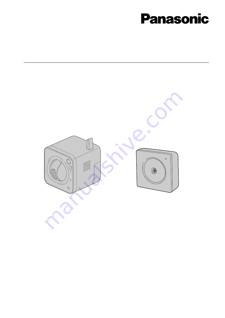
BL-VT164 Series
BL-VP100 Series
BL-VT164W
BL-VP104W
This manual covers the models: BL-VT164 Series (BL-VT164W, BL-VT164, BL-VT164WE, BL-VT164E,
BL-VT164WU, BL-VT164U, BL-VT164WBR) and BL-VP100 Series (BL-VP104W, BL-VP104, BL-VP101,
BL-VP104WE, BL-VP104E, BL-VP101E, BL-VP104WU, BL-VP104U, BL-VP101U, BL-VP104WBR).
Before attempting to connect or operate this product, please read these instructions carefully and save this
manual for future use.
The model number is abbreviated in some descriptions in this manual.


