


2
Connections
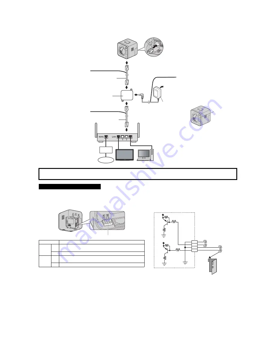
Connect the camera to your router and to the power outlet as described below.
• Before proceeding, confirm that your PC is connected to your router and can access the Internet. Also confirm that your router’s UPnP
™
feature is
enabled. (Most routers have UPnP
™
turned off by default.) Refer to the operating instructions included with your router or to the Panasonic Network
Camera website (http://panasonic.net/pcc/ipcam/) for more information.
• Use a LAN cable that is no more than 30 m (98 feet 5 inches) long to connect the camera and the power transfer unit.
The camera’s external INPUT interface allows you to connect a device, such as a sensor or motion detector, that can be used to trigger the camera’s image
buffering and transferring features (see Section 2 Using Triggers to Buffer and Transfer Images in the Operating Instructions on the CD-ROM), as well as
the detection notification sound feature (see Section 1.2.11 Additional Features Available While Viewing Live Camera Images in the Operating Instructions
on the CD-ROM).
1
Connect the LAN cable to the
camera and the power transfer
unit.
2
Connect the LAN cable to the
router and the power transfer unit.
3
Connect the AC adaptor to the power
transfer unit and plug the AC adaptor
into the power outlet.
• Confirm that the indicator turns
green after about 1 minute. If it does
not turn green, see 1.2 POWER
Indicator Issues in the
Troubleshooting Guide on the CD-
ROM.
• When you operate the camera, the
power outlet should be near the
camera and easily accessible.
• Use only specified Panasonic AC
adaptor (Order No. PQLV206Y for
BL-C210A, PQLV206CEY for
BL-C210CE, and PQLV206EY for
BL-C210E).
• The camera may become warm.
This is normal.
After the camera’s indicator turns green, you may set up the camera. Continue by following the procedure described
in the included Setup Guide.
• If the indicator does not turn green, see 1.2 POWER Indicator Issues in the Troubleshooting Guide on the included CD-ROM.
Connecting External INPUT interface
Caution
• The external INPUT interface is not capable of connecting directly to
devices that require large amounts of current. In some cases, a
custom interface circuit (customer-provided) may have to be used.
Serious damage to the camera may result if a device that exceeds
its electrical capability is connected to the external INPUT interface.
• Low voltage/current circuits and high voltage/current circuits are
used in the camera circuit. All wiring should be performed by a
qualified electrician. Incorrect wiring could damage the camera and
cause a fatal electric shock.
Terminal
Description
IN1
1
External sensor input. The camera can be triggered by either an open
circuit or a GND short-circuit.
2
GND terminal.
IN2
3
External sensor input. The camera can be triggered by either an open
circuit or a GND short-circuit.
4
GND terminal.
Note
• If excessive force is used when disconnecting wires with pointed objects from
the external INPUT interface, terminals may become damaged or the interface
may be pushed inside the camera body and become unusable.
VIERA
(BL-C210A only)
LAN cable
(Cat-5 straight cable)
Power transfer unit
LAN cable
AC adaptor
To the power
outlet
Router
Modem
Internet
PC
Green
External INPUT interface
Door Sensor 1 (Alarm 1)
Door Sensor 2 (Alarm 2)
Camera
Circuit Diagram Example
2
4
3
1


