


2005 Panasonic Communications Co., Ltd. All Rights Reserved.
PSQX3859ZB
KK0605YT2056
Getting Started
Network Camera Server
Model No.
BB-HCS301A
•
Please read the Installation manual before using.
•
This Getting Started explains how to connect and set up this product.
See the Operating Instructions on the Setup CD-ROM for details about
the features.
•
If you cannot complete the setup, see the Troubleshooting manual on the
Setup CD-ROM.
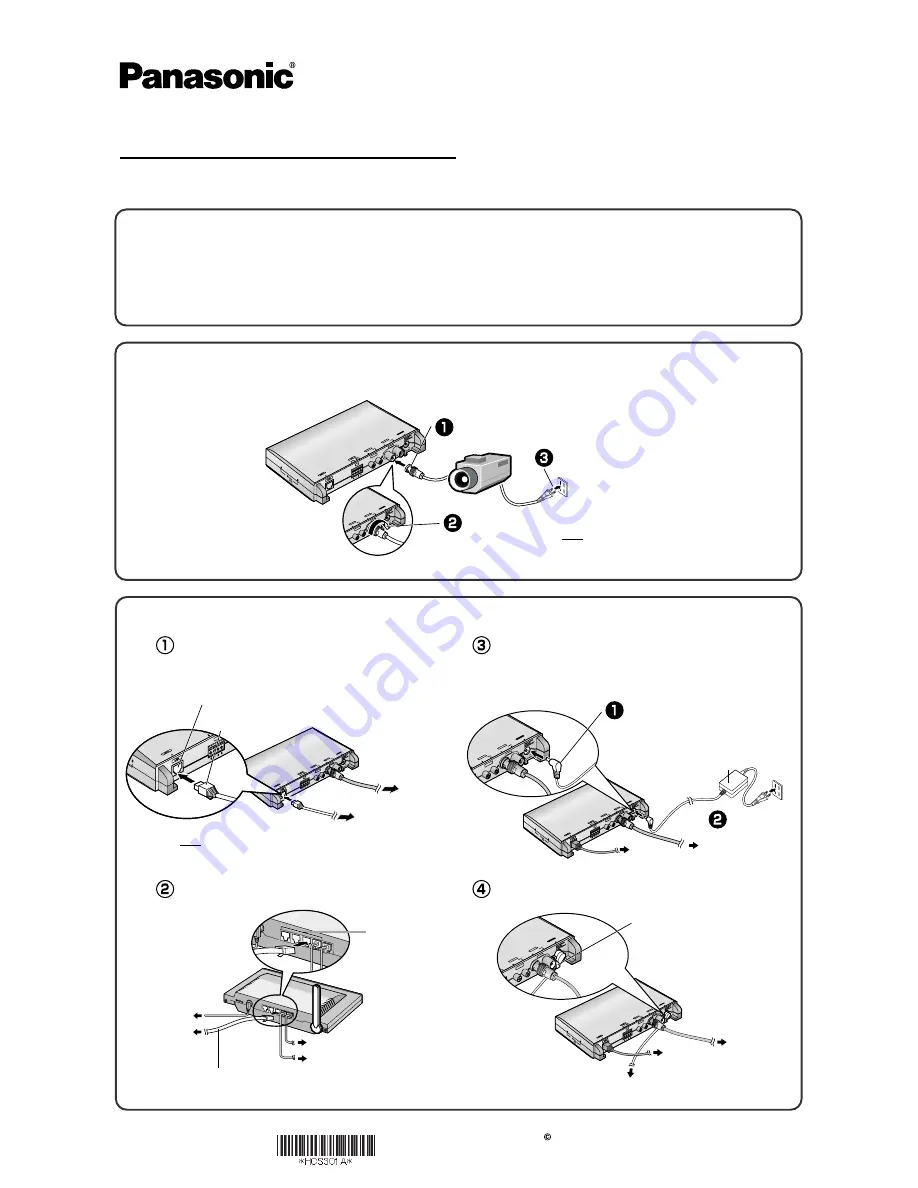
2.
Connect this product to your router, and turn this product on.
1.
Connect the video cable (BNC terminal) to this product's video input terminal, and
turn the camera on.
•
If the indicator does not light green, see page 3 and page 4 of the
Troubleshooting on the Setup CD-ROM.
•
Use only specified Panasonic AC adaptor PQLV202 (Order No.
PQLV202Y).
This product will be connected to your router using a "straight" Cat5
network cable (customer-provided).
Connect the Ethernet cable (customer-provided)
to your router.
Trademarks
•
Adobe, Acrobat and Reader are either registered trademarks or trademarks of Adobe Systems Incorporated in the United States and/or other countries.
•
Microsoft, Windows and ActiveX are either registered trademarks or trademarks of Microsoft Corporation in the United States and/or other countries.
•
Screen shots reprinted with permission from Microsoft Corporation.
•
All other trademarks identified herein are the property of their respective owners.
•
This software is based in part on the work of the Independent JPEG Group.
Abbreviations
•
UPnP is the abbreviation for "Universal Plug and Play".
•
"Network Camera" or the "Analog Camera connected to this product" is called "Camera" in this manual.
Connect the Ethernet cable (customer-provided)
to this product.
Connect the AC adaptor to this product.
Put an AC adaptor cord through an AC adaptor hook.
Note
In advance, adjust the image display on the monitor
such as a position, etc.
Note
In advance, make your PC connected to the Internet. See the
router's manual for the Internet access.
IN
DC
IN
IN
IN
AU
DIO
UDIO
VID
EO
VIDEO
PO PO
W
ER
WER
IN
IN
OU
T
OUT
IN
IN
OUT
OUT
IN
IN
OU
T
OUT
AU
DIO
UDIO
I/O
I/O
VID
EO
VIDEO
12
12V
IN
DC
IN
IN
AU
DIO
UDIO
VID
EO
VIDEO
PO PO
W
ER
WER
IN
IN
OU
T
OUT
IN
IN
OUT
OUT
N
IN
OUT
OUT
AU
DIO
UDIO
I/O
I/O
VID
EO
VIDEO
12V
Hook
To your router
To the supply
To your camera
IN
DC
IN
IN
IN
AU
DIO
UDIO
VID
EO
VIDEO
PO PO
W
ER
WER
IN
IN
OUT
OUT
IN
IN
OU
T
OUT
IN
OU
T
OUT
AUDIO
UDIO
I/O
I/O
VIDEO
VIDEO
12
12V
To your camera
To
your router
Plug the AC cord
into the outlet.
AC adaptor
IN
DC IN
IN
AUDIOUDIO
VIDEO
VIDEO
PO
PO
WER
WER
IN
OUT
OUT
IN
IN
OU
T
OUT
IN
OU
T
OUT
AUDIO
UDIO
I/O
VIDEO
VIDEO
12V
Connect the plug to the DC IN jack.
To your modem
To your PC
To the supply
To this product
Ethernet cable
(Straight Cat5 cable)
(Customer-provided)
To LAN jack
IN
DC
IN
IN
IN
AU
DIO
UDIO
VID
EO
VIDEO
PO PO
W
ER
WER
IN
IN
OU
T
OUT
IN
OU
T
OUT
IN
OU
T
OUT
AU
DIO
UDIO
I/O
I/O
VI
DE
O
VIDEO
To your camera
To your router
IN
AUDIO
VIDEO
PO
WER
IN
OUT
IN
OUT
IN
OUT
AUDIO
I/O
I/O
VIDEO
12V
Ethernet (LAN) port
Ethernet cable
(customer-provided)
12
12V
Connect the power cord
IN
DC
IN
IN
IN
AU
DIO
UDIO
VID
EO
VIDEO
PO PO
W
ER
WER
IN
OU
T
OUT
IN
IN
OUT
OUT
IN
IN
OU
T
OUT
AUDIO
UDIO
I/O
VIDEO
VIDEO
Fit the plug's groove to this product's video input terminal.
IN
DC
IN
IN
AU
DIO
UDIO
VID
EO
VIDEO
PO PO
W
ER
WER
IN
OUT
OUT
IN
OUT
OUT
IN
OU
T
OUT
AU
DIO
UDIO
I/O
VID
EO
VIDEO
12V
12
12V
Turn the grip right.


