


3
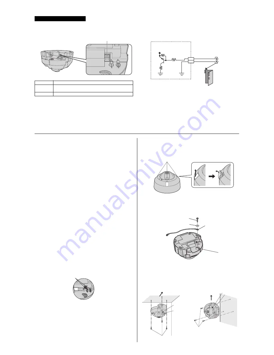
The camera’s external INPUT interface allows you to connect a device (such as sensors, motion detectors, etc.) that can be used to trigger the camera’s image
buffering and transferring features (see Section 2 Using Triggers to Buffer and Transfer Images in the Operating Instructions on the CD-ROM).
The external INPUT interface has 2 terminals.
Mounting the Camera
Important Information Regarding Camera Mounting
Please read the following information before mounting the camera. Consult an
authorized dealer for mounting.
Caution
• Make sure you attach the safety wire when mounting the camera on a
ceiling to prevent the camera from falling.
Note
• The camera is intended for indoor use only and should not be mounted
outdoors.
• The included screws are for use with wooden ceilings only.
• Use screws that are appropriate for the material of ceiling.
• If the ceiling or wall material is mortar or concrete, see page 4 “When
mounting the camera on a concrete or mortar ceiling”.
• Do not drive the screws into a soft material. Drive the screws into a secure,
25 mm (1 inch) thick area of the ceiling or wall, such as a crossbeam,
otherwise the camera may fall. If there is no crossbeam, place a board on
the other side of the ceiling or wall to make sure the camera is securely
mounted.
• The pull-out strength of the installation area must be at least 294 N (30 kgf)
per screw.
• Mount the camera to a flat horizontal ceiling surface or vertical wall. (The
camera cannot be used on surfaces that have more than a 15° slant.)
• The camera cover must be removed in order to insert or remove the SD
memory card.
• The camera’s MAC address and serial number are printed on the bottom of
the camera and are needed in order for camera configuration and
maintenance. Make a note of both of them before mounting the camera.
• Mounting and cabling instructions described in this document follow
generally accepted guidelines suitable for residential installations. In some
areas, commercial and industrial installations are regulated by local or state
ordinances. For such installations, contact your local building department or
building inspector for more details.
• Camera images can be viewed in relatively dark areas, however, image
quality decreases when viewing dark images. We recommend using
supplemental lighting for best results.
• Prolonged exposure to direct sunlight or halogen light may damage the
camera’s image sensor. Mount the camera appropriately.
• Do not directly touch the lens cover. Clean the lens cover with a dry and soft
cloth if necessary.
• When mounting the camera, make sure to wrap the AC adaptor cord (if
used) around the hooks as shown to ensure secure connections.
• Adjust the installation location and the direction the camera is facing while
watching the actual camera image being displayed on a computer screen.
Mounting the Camera
Wiring without making a hole for cables in the ceiling or wall
1.
Open the screw covers, loosen the screws, and remove the camera
cover. (
For BB-HCM701CE/BB-HCM705CE:
When loosening the
screws, use the included bit.)
2.
Secure the safety wire to the camera using screw B (included) and
washer B (included).
• Make sure you attach the safety wire when mounting the camera on a
ceiling to prevent the camera from falling. (Recommended torque
0.6 N·m {6.1 kgf·cm})
3.
Connect all necessary cables (AC adaptor, LAN, etc.).
4.
Secure the camera to the ceiling or wall using screws A (included).
• Do not drive the screws into a soft material. Drive the screws into a
secure, 25 mm (1 inch) thick area of the ceiling or wall, such as a
crossbeam, otherwise the camera may fall. If there is no crossbeam,
place a board on the other side of the ceiling or wall to make sure the
camera is securely mounted.
Connecting External Sensors
Note
• Do not push strongly on the external INPUT interface with the pointed
object. The external INPUT interface may get stuck into the unit, and you
may not be able to use it.
Terminal
Description
1
External sensor input. The camera can be triggered by either an open
circuit or a GND short-circuit.
2
GND terminal.
Caution
• The external INPUT interface is not capable of connecting directly to
devices that require large amounts of current. In some cases, a custom
interface circuit (customer-provided) may have to be used. Serious
damage to the camera may result if a device that exceeds its electrical
capability is connected to the external INPUT interface.
• Low voltage/current circuits and high voltage/current circuits are used in
the camera circuit. All wiring should be performed by a qualified electrician.
Incorrect wiring could damage the camera and cause a fatal electric shock.
External INPUT interface
Door Sensor (Alarm)
Camera
Circuit Diagram Example
1
2
Cable hook
N
Ceiling
N
Wall
Screw covers (3 places)
Safety wire hole
Screw B
(Length: 10 mm [3/8 inches],
Body diameter: 2.6 mm [1/8 inches])
Washer B
(Inside diameter: 2.6 mm [1/8 inches])
Safety wire
Screws A (3 pcs.)
(Length: 20 mm [13/16 inches],
Body diameter: 4.0 mm [3/16 inches])
Microphone
Indicator
Front
Microphone
Indicator
Screws A (3 pcs.)
(Length: 20 mm [13/16 inches],
Body diameter: 4.0 mm [3/16 inches])
Up


