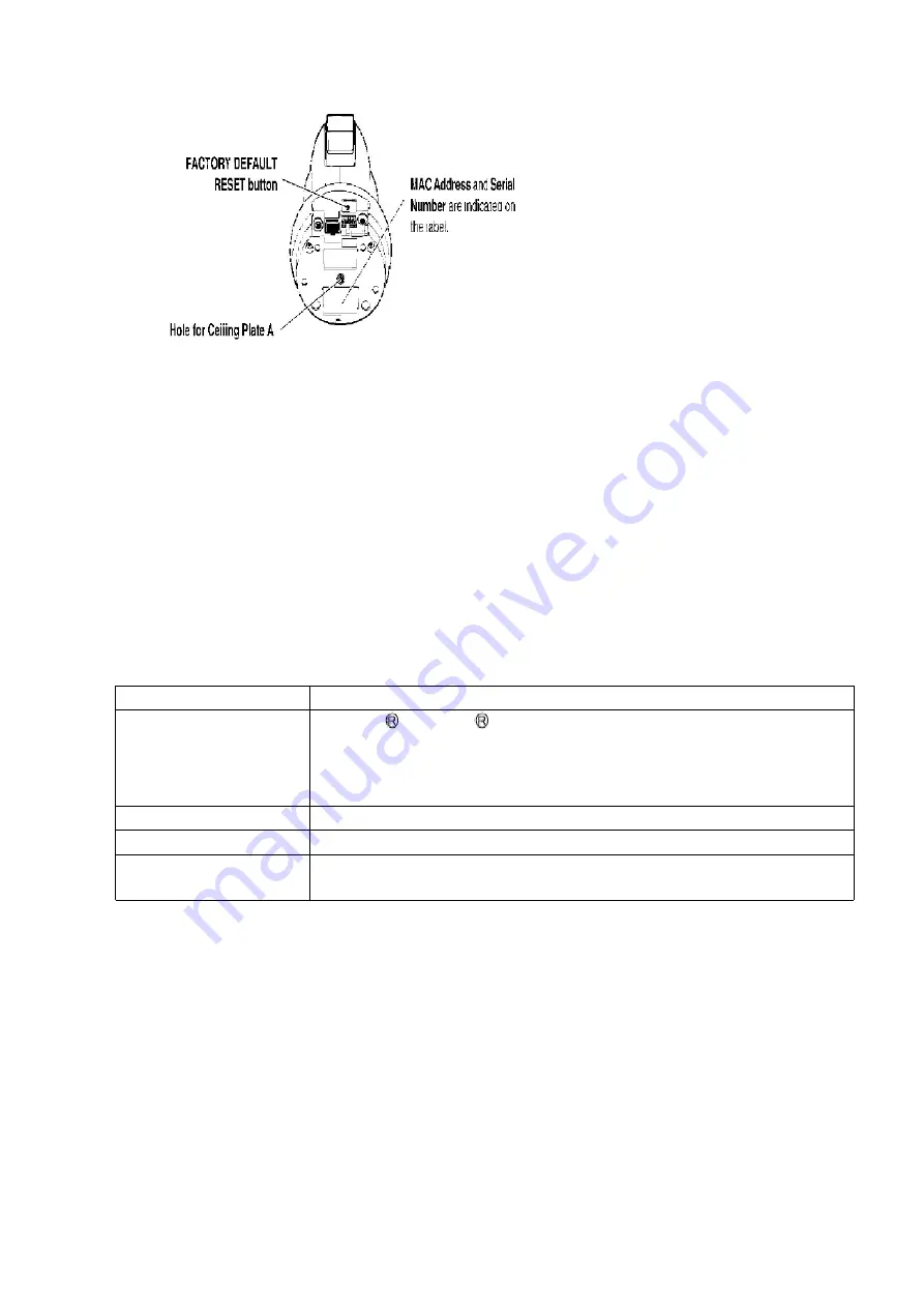
7. CONNECTING YOUR NETWORK CAMERA
7.1. PREPARATION
Prepare the following before connecting the Network Camera.
- PC to fulfill the system requirements.
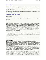
SYSTEM REQUIREMENTS
The PC (Personal Computer) and the network must meet the following technical specifications for the
Network Camera to work properly.
Item
Description
Operation System
Microsoft Windows 98SE operating system
Microsoft Windows 2000 operating system
Microsoft Windows Me operating system
Microsoft Windows XP operating system
Network Protocol
TCP/IP network protocol installed. (HTTP, TCP, UDP, IP, DNS, ARP, ICMP)
Interface
10/100Mbps Ethernet card for your network connection
Web Browser
Internet Explorer 6.0 or later
(Not included on the Setup CD-ROM).
Note:
Pentium II 300 MHz or greater CPU is recommended to prevent performance degradation.
- Ethernet switching Hub or wireless Router for LAN Connection.
- Ethernet cable (two pieces of Category 5 straight cable, or a piece of
Category 5 cross cable).
- Setup CD-ROM
The setup program simplifies Network Camera installation. Adobe
Acrobat Reader 4.05 or later enables you to see the Operating
15
Summary of Contents for BB-HCM381A - Network Camera
Page 4: ...Lens Board 4 ...
Page 5: ...Video Board CCD Board 5 ...
Page 19: ...2 Make a hole for a cable 19 ...
Page 24: ...1 Remove three Screws C And remove the Cabinet Cover 24 ...
Page 25: ...2 Remove the Screw B And remove the I O Board 25 ...
Page 28: ...3 Remove eight Screws A 4 Remove the Upper Tilt Cover And remove the Lower Tilt Cover 28 ...
Page 30: ...4 Remove the Tilt Belt 5 Remove the Tilt Block Ass y Camera Unit 30 ...
Page 37: ...When fix Lens Board by the Screws please use the jig not to shift Lens Guide Ass y 37 ...
Page 38: ...10 6 CCD UNIT 38 ...
Page 48: ...12 TROUBLE SHOUTING 12 1 STARTUP OPERATION 12 2 OTHER FUNCTION CHECK 48 ...
Page 49: ...12 3 IMAGES BLOCK CHECK 49 ...
Page 50: ...50 ...
Page 51: ...12 4 CAMERA UNIT CHECK 51 ...
Page 52: ...52 ...
Page 53: ...12 5 LENS PCB CHECK 53 ...
Page 54: ...54 ...
Page 55: ...12 5 1 ZOOM Operation Check 55 ...
Page 56: ...12 6 SOUND BLOCK CHECK 56 ...
Page 57: ...12 6 1 External Microphone 57 ...
Page 58: ...12 6 2 Speaker Output 12 6 3 Common Flow for External Microphone and Speaker Output 58 ...
Page 59: ...12 7 PAN TILT OPERATION CHECK 12 7 1 PAN Operation Check 59 ...
Page 60: ...12 7 2 TILT Operation Check 60 ...
Page 61: ...12 8 LAN BLOCK CHECK 61 ...
Page 62: ...12 9 SD CARD CHECK 62 ...
Page 63: ...63 ...
Page 64: ...12 10 POWER SUPPLY BLOCK CHECK 64 ...
Page 65: ...65 ...
Page 66: ...12 11 RTC CIRCUIT CHECK 66 ...
Page 67: ...12 12 I O TERMINAL CHECK 67 ...
Page 68: ...12 13 LED CIRCUIT CHECK 68 ...
Page 69: ...12 14 INITIALIZATION OPERATION CHECK 69 ...
Page 70: ...12 15 VERSION UPGRADE CHECK 70 ...
Page 93: ...19 ACCESSORIES AND PACKING MATERIALS 93 ...
Page 94: ...20 REPLACEMENT PARTS LIST Note 1 RTL Retention Time Limited 94 ...
Page 99: ...C156 ECJ0EF1C104Z 0 1 99 ...
Page 101: ...C239 ECJ0EC1H101J 100p 101 ...
Page 103: ...C430 ECJ0EC1H101J 100p 103 ...
Page 105: ...L402 PQLQR1KT COIL S 105 ...
Page 107: ...R202 ERJ2GEJ470 47 107 ...
Page 110: ...110 ...
Page 117: ...C901 ECUV1A105ZFV 1 117 ...
Page 119: ...C1169 ECJ0EF1C104Z 0 1 119 ...
Page 121: ...R838 ERJ3EKF5601 5 6k 121 ...
Page 125: ...C537 ECUV1C104ZFV 0 1 125 ...
Page 129: ...23 11 I O BOARD COMPONENT VIEW 23 12 I O BOARD BOTTOM VIEW A BBHCM381A 129 ...
Page 132: ...IC1101 7 1 8 14 BB HCM381A CCD BOARD BOTTOM VIEW ...
Page 142: ...C B A D E1 E2 ...
Page 143: ...F3 F2 G2 E3 F1 G1 ...
Page 144: ...I1 I2 I3 K1 K2 K3 K4 Tilt Scan L1 L2 M1 M2 H2 H3 H4 H5 J1 J2 J3 ...
Page 146: ...P6 P7 P8 P9 10Base Hub Connection Communicating Q R1 R2 S1 S2 S3 T1 P5 ...
Page 147: ...V W1 W3 W4 W2 X1 X2 X3 T2 ...
Page 148: ...X6 Y4 Y1 Y2 Y3 Z1 Z2 Z3 Z4 X4 X2 X3 X5 ...
Page 149: ...a1 a2 a3 b1 b2 b3 b4 Pan Scan ...


