background image

Narrow pitch connectors 

A35US

 with power terminal (0.35mm pitch)

–2–

ACCTB78E   201510-T

PRODUCT TYPES

Notes: 1. Order unit: 

For volume production: 1-inner carton (1-reel) units
For samples, please contact our sales office.

2. Please contact us for connectors having a number of pins other than those listed above.

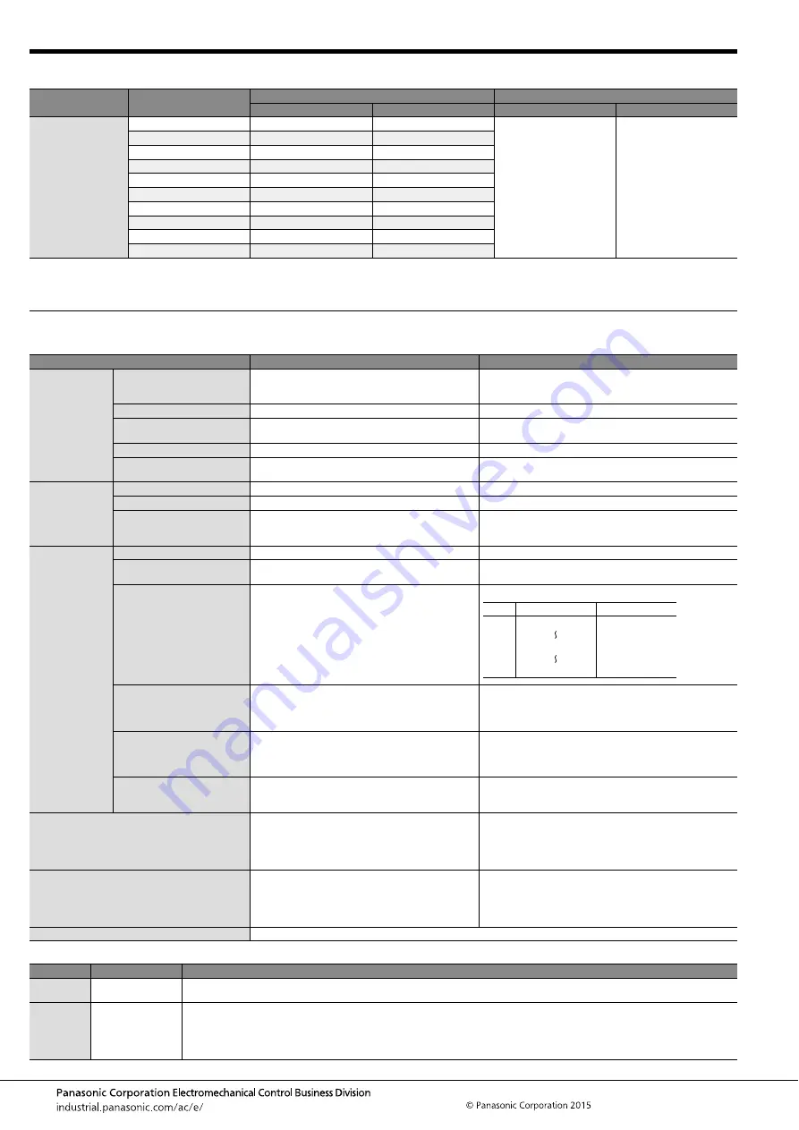
SPECIFICATIONS

1. Characteristics

2. Material and surface treatment

Mated height

Number of pins

Part number

Packing

Socket

Header

Inner carton (1-reel)

Outer carton

0.6mm

10

AXG7100J7

AXG8100J4

10,000 pieces

20,000 pieces

12

AXG7120J7

AXG8120J4

16

AXG7160J7

AXG8160J4

20

AXG7200J7

AXG8200J4

24

AXG7240J7

AXG8240J4

30

AXG7300J7

AXG8300J4

34

AXG7340J7

AXG8340J4

40

AXG7400J7

AXG8400J4

50

AXG7500J7

AXG8500J4

60

AXG7600J7

AXG8600J4

Item

Specifications

Conditions

Electrical
characteristics

Rated current

3.0A/pin contact (power terminal)
0.30A/pin contact (signal terminal): Max. 5 A at total 
pin contacts

Rated voltage

60V AC/DC

Breakdown voltage

150V AC for 1 min.

No short-circuiting or damage at a detection current of 1 mA 
when the specified voltage is applied for one minute.

Insulation resistance

Min. 1,000M

Ω

 (initial)

Using 250V DC megger (applied for 1 min.)

Contact resistance

Max. 30m

Ω

 (power terminal)

Max. 90m

Ω

 (signal terminal)

Based on the contact resistance measurement method 
specified by JIS C 5402.

Mechanical
characteristics

Composite insertion force

1.300N/pin contacts 

×

 pin contacts

Composite removal force

0.165N/pin contacts 

×

 pin contacts

Contact holding force 
(Socket signal terminal, 
Header power terminal)

Min. 0.20N/pin contacts

Measuring the maximum force.
As the contact is axially pull out.

Environmental
characteristics

Ambient temperature

–55

°

C to +85

°

C

No freezing at low temperatures. No dew condensation.

Storage temperature

–55

°

C to +85

°

C (product only)

–40

°

C to +50

°

C (emboss packing)

No freezing at low temperatures. No dew condensation.

Thermal shock resistance
(header and socket mated)

5 cycles,
insulation resistance min. 100M

Ω

,

contact resistance max. 30m

Ω

 (power terminal)

max. 90m

Ω

 (signal terminal)

Conformed to MIL-STD-202F, method 107G

Humidity resistance
(header and socket mated)

120 hours,
insulation resistance min. 100M

Ω

,

contact resistance max. 30m

Ω

 (power terminal)

max. 90m

Ω

 (signal terminal)

Conformed to IEC60068-2-78
Bath temperature 40

±

2

°

C,

humidity 90 to 95% R.H.

Saltwater spray resistance
(header and socket mated)

24 hours,
insulation resistance min. 100M

Ω

,

contact resistance max. 30m

Ω

 (power terminal)

max. 90m

Ω

 (signal terminal)

Conformed to IEC60068-2-11
Bath temperature 35

±

2

°

C,

saltwater concentration 5

±

1%

H

2

S resistance

(header and socket mated)

48 hours,
contact resistance max. 30m

Ω

 (power terminal)

max. 90m

Ω

 (signal terminal)

Bath temperature 40

±

2

°

C, gas concentration 3

±

1 ppm, 

humidity 75 to 80% R.H.

Insertion and removal life

Mechanical life: 30 times
Contact resistance max. 30m

Ω

 (power terminal)

max. 90m

Ω

 (signal terminal)

Composite removal 
force 0.165N/pin contacts 

×

 pin contacts

Repeated insertion and removal speed of max. 200 times/
hours

Soldering heat resistance

The initial specification must be satisfied electrically 
and mechanically

Infrared reflow soldering: Peak temperature: 260

°

C or less 

(on the surface of the PC board 
around the connector terminals)

Soldering iron: 300

°

C within 5 sec.

350

°

C within 3 sec.

Unit weight

60 pin contacts: Socket 0.02g  Header 0.01g

Part name

Material

Surface treatment

Molded 

portion

LCP resin 

(UL94V-0)

Contact and 

Post

Copper alloy

Contact portion:  Base: Ni plating, Surface: Au plating
Terminal portion: Base: Ni plating, Surface: Au plating (except the terminal tips)
                                      The terminals close to the portion to be soldered have nickel barriers (exposed nickel portions).
Power terminals: Sockets:  Base: Ni plating, Surface: Au plating (except the terminal tips)

Headers: Base: Ni plating, Surface: Au plating

Order Temperature (

°

C)

Time (minutes)

1
2
3
4

–55

85

–55

0

3

30

Max. 5

30

Max. 5

+

3

0

0

3

Summary of Contents for AXG7100J7

Page 1: ...CATIONS Multiple connection of power signal between USB and battery in portable terminals such as smartphones and tablet PCs Socket 2 2m m 1 8m m Header RoHS compliant Socket 2 2mm 1 8mm Header Power terminals Specification 3 A in two locations 3 5mm 3 5mm Example Charging current Max 3 0 A 0 3 A pin Pitch 0 35 mm 20 pins signal terminals used Product without power terminals 20 pins signal termina...

Page 2: ...ng at low temperatures No dew condensation Thermal shock resistance header and socket mated 5 cycles insulation resistance min 100MΩ contact resistance max 30mΩ power terminal max 90mΩ signal terminal Conformed to MIL STD 202F method 107G Humidity resistance header and socket mated 120 hours insulation resistance min 100MΩ contact resistance max 30mΩ power terminal max 90mΩ signal terminal Conform...

Page 3: ...Y and Z parts are connected electrically Dimension table mm Number of pins dimension A B C 10 4 25 1 40 3 45 12 4 60 1 75 3 80 16 5 30 2 45 4 50 20 6 00 3 15 5 20 24 6 70 3 85 5 90 30 7 75 4 90 6 95 34 8 45 5 60 7 65 40 9 50 6 65 8 70 50 11 25 8 40 10 45 60 13 00 10 15 12 20 CAD Data A B 0 1 0 35 0 05 0 12 0 03 The degree of terminal flat 0 46 1 80 1 42 0 80 Suction face Post and Power terminal 0 ...

Page 4: ...Tape I 16 0 7 5 17 4 10 000 40 to 60 Tape I 24 0 11 5 25 4 10 000 Specifications for taping In accordance with JIS C 0806 3 1999 However not applied to the mounting hole pitch of some connectors Specifications for the plastic reel In accordance with EIAJ ET 7200B Leading direction after packaging 1 75 B A 2 0 4 0 4 0 0 3 0 1 1 5 d i a 0 1 0 Tape I Top cover tape Embossed carrier tape Embossed moun...

Page 5: ...tern TOP VIEW Recommended metal mask pattern Metal mask thickness When 100μm Terminal opening ratio 70 Metal part opening ratio 46 Header Mated height 0 6 mm Recommended PC board pattern TOP VIEW Recommended metal mask pattern Metal mask thickness When 100μm Signal terminal opening ratio 70 Power terminal opening ratio 77 1 2 C 0 1 5 0 35 0 03 0 20 0 03 2 50 0 03 1 60 0 03 0 20 0 03 0 50 1 04 0 03...

Page 6: ... dimensions given 5 PC board Control the thicknesses of the coverlay and adhesive to prevent poor soldering This connector has no stand off Therefore minimize the thickness of the coverlay etc so as to prevent the occurrence of poor soldering 6 For all connectors of the narrow pitch series to prevent the PC board from coming off during vibrations or impacts and to prevent loads from falling direct...

Page 7: ...ctor before mounting 9 Consult us when using a screen printing thickness other than that recommended Hand soldering 1 Set the soldering iron so that the tip temperature is less than that given in the table below Table A 2 Do not allow flux to spread onto the connector leads or PC board This may lead to flux rising up to the connector inside 3 Touch the soldering iron to the foot pattern After the ...

Page 8: ...ring avoid storing the connectors in areas of high humidity 2 Depending on the connector type the color of the connector may vary from connector to connector depending on when it is produced Some connectors may change color slightly if subjected to ultraviolet rays during storage This is normal and will not affect the operation of the connector 3 When storing the connectors with the PC boards asse...

Page 9: ...ne connectors are delivered in 50 piece units in the condition given right Consult a sale representative for ordering sample units Condition when delivered from manufacturing Required number of products for sample production Unit 50 pcs Embossed tape amount required for the mounting Reel Delivery can also be made on a reel by customer request Please refer to the latest product specifications when ...

Reviews: