background image

12

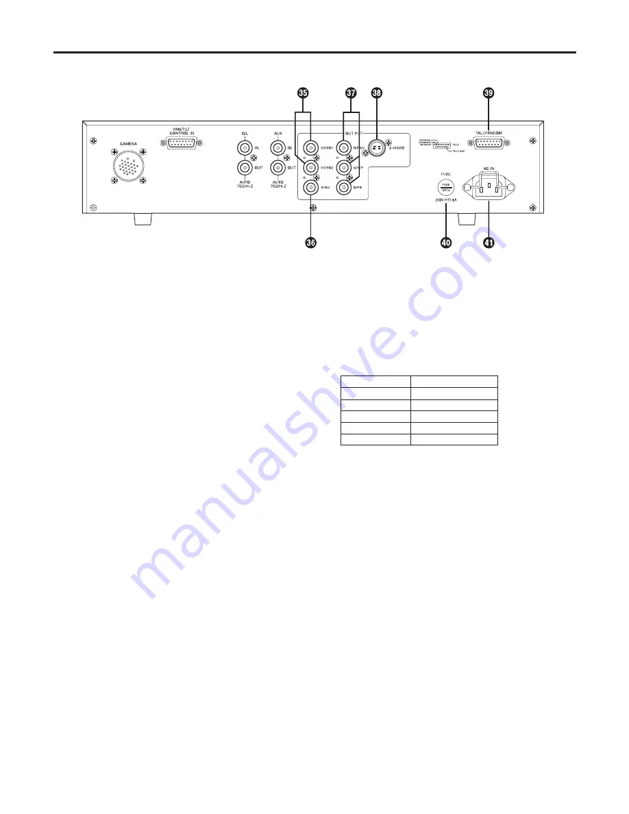
 Video output connectors [VIDEO1, VIDEO2]

The video signals from the camera after cable 
compensation are output from these connectors. (The 
same signal is output from connectors 1 and 2.)
Connect the connectors to the video input connectors 
on the live switcher, color monitor, VTR or other device. 
(Output impedance: 75 ohms)

 SYNC output connector [SYNC]

The composite sync signal is output from this connector. 
Connect the connector to the gen-lock input connector on 
the color monitor or other device.  
(Output impedance: 75 ohms)

  RGB/Y, PR and PB/YC output connectors  

[R/PR/C, G/Y/Y, B/PB]

If a camera such as the AW-E650 with RGB/Y, PR and 
PB/YC signal output facilities is connected to the remote 
control unit, its signals are output from these connectors. 
(Output impedance: 75 ohms)
The RGB/Y, PR or PB/YC signals are selected using 
the camera’s menu. (For details, refer to the camera’s 
operating instructions.)

  S-Video output connector [S-VIDEO OUT]  

(4-pin S-connector)

The same signals as the ones output from the R/PR/C 
and G/Y/Y connectors among the RGB/Y, PR and PB/YC 
output connectors 

 are output from this connector. 

(Output impedance: 75 ohms)
The YC signals are selected using the camera’s menu, 
and connected to a color monitor or other device 
equipped with an S-Video input connector.

Note:


When the RGB/Y, PR and PB/YC output connectors 


and S-Video output connector 

 are used at the same 

time, the level of the output signals will be reduced. 
Therefore, use either connectors 

 or connector 

 in 

line with the connectors used on the device connected to 
the remote control unit.

  Tally/intercom input/output connector  

[TALLY/INCOM] (D-SUB 15-pin connector)

Connect this to the TALLY & INCOM connector on the live 
switcher (AW-SW350). 
Set the INCOM selector switch on the live switcher 
(AW-SW350) to [3-wire type].
When inputting the tally control signals from another 
device, input them with 0V for ON and open for OFF.

Pin No.

Signal Name

1

TALLY

6

INCOM MIC

7

INCOM GND

8

INCOM SP

11

TALLY GND

 Fuse holder [FUSE]

Fuse used: HT1.6AN5 (AC 250 V, 1.6 A)

 AC power socket [AC IN]

Attach one end of the power cord provided to this socket 
and the other end to the AC 120V (60 Hz) power supply.

Parts and their functions

Summary of Contents for AWRC600P - REMOTE CONTROL UNIT

Page 1: ...Before attempting to connect operate or adjust this product please read these instructions completely Remote Control Unit AW RC600P ...

Page 2: ...RATUS CAUTION TO REDUCE THE RISK OF FIRE OR SHOCK HAZARD AND ANNOYING INTERFERENCE USE THE RECOMMENDED ACCESSORIES ONLY FCC Note This equipment has been tested and found to comply with the limits for a class A digital device pursuant to Part 15 of the FCC Rules These limits are designed to provide reasonable protection against harmful interference when the equipment is operated in a commercial env...

Page 3: ...ence receptacles and the point where they exit from the apparatus 11 Only use attachments accessories specified by the manufacturer 12 Use only with the cart stand tripod bracket or table specified by the manufacturer or sold with the apparatus When a cart is used use caution when moving the cart apparatus combination to avoid injury from tip over 13 Unplug this apparatus during lightning storms o...

Page 4: ...h viewfinder 328 ft 100 m Cables AW CA50A26 RCU cable 49 2 ft 15 m WV CA26U15 Studio cable for extension 49 2 ft 15 m WV CA26U30 Studio cable for extension 98 4 ft 30 m WV CA26U100 Studio cable for extension 328 ft 100 m WV CA26T26 Joint connector for extension Introduction 4 Accessories 4 Precautions for use 5 Parts and their functions 6 Front panel 6 Rear panel 11 Connections 13 Operating proced...

Page 5: ...he cables Be absolutely sure to turn off the power before connecting or disconnecting the cables AC 120 V is the unit s rated supply voltage Be absolutely sure to supply an AC 120 V voltage to the unit Maintenance Wipe the unit using a dry cloth To remove stubborn dirt dip a cloth into a diluted solution of kitchen detergent wring it out well and wipe the unit gently Precautions for use Caution Av...

Page 6: ...output cannot be obtained even by setting the lens iris to wide open set it to 9 dB or 18 dB AGC selector switch AGC HIGH LOW OFF HIGH At this setting the maximum AGC gain is set to 30 dB This value may differ according to the camera used LOW At this setting the maximum AGC gain is set to 18 dB This value may differ according to the camera used OFF AGC does not function Select the gain using the g...

Page 7: ...hting subject or other aspects and try performing the automatic adjustment again If the black balance has not ended successfully close the lens iris completely and try performing the automatic adjustment again White balance selector switch AWC ATW ATW A B This switch is used to select the auto white balance setting ATW At this setting the camera provides compensation in such a way that the white b...

Page 8: ...ght mode 2 Fluorescent light mode 3 Outdoor mode Select the scene file which is optimally suited to the shooting conditions For details refer to the camera s operating instructions Electronic shutter selector switch SHUTTER OFF 100 500 1000 S S ELC This switch enables the shutter speed OFF 1 100 1 500 1 1000 as well as S S and ELC to be selected S S This stands for synchro scan The shutter speed c...

Page 9: ...n Note The ALC cannot be finely adjusted and the lens iris cannot be adjusted when the iris selector switch on the lens is set to a position other than AUTO such as MANU With some lenses the open and close directions with respect to the control directions may be reversed If this is the case contact the lens manufacturer or your dealer Intercom connector INCOM XLR 4 pin connector A headset is conne...

Page 10: ...ount is also varied by this control Chroma gain adjustment control ADJUST CHROMA This is used to adjust the chrominance level of the video output signals to match the cable length Select the cable length using the cable compensation selector switch and adjust the Y level of the video output signals using the Y gain adjustment control before adjusting the level Menu ON OFF switch MENU OFF ON OFF On...

Page 11: ... the LEFT and RIGHT pins are not connected to the COMM pin at the same time Similarly do not connect both the UP and DOWN FAR and NEAR or WIDE and TELE pins to the COMM pin at the same time Pins 12 to 15 are used when exercising lens control only To do this connect the controller s FOCUS CONT pin to NEAR pin 6 and its ZOOM CONT pin to WIDE pin 8 Normally pins 12 to 15 are not used when exercising ...

Page 12: ...ut from the R PR C and G Y Y connectors among the RGB Y PR and PB YC output connectors are output from this connector Output impedance 75 ohms The YC signals are selected using the camera s menu and connected to a color monitor or other device equipped with an S Video input connector Note When the RGB Y PR and PB YC output connectors and S Video output connector are used at the same time the level...

Page 13: ...ideo signals select Y C using the camera s menu Furthermore use either the S Video connector or BNC connectors and leave the other connectors unconnected The S Video connector and BNC connectors cannot be used at the same time Connect either the VIDEO OUT BNC connector or S Video connector to the AW SW350 live switcher Use an intercom headset suited to all the devices Fabricate the TALLY INCOM cab...

Page 14: ...at the unit will be used under the same conditions When the white balance selector switch is used at the ATW setting the white balance need not be adjusted 4 Adjust the black balance This adjustment must be performed when the unit is used for the first time or when the unit has not been used for a prolonged period It must also be performed when the ambient temperature has changed significantly or ...

Page 15: ... only 2 Connect the wave form monitor or oscilloscope and vectorscope to the video output connectors 75 ohms termination 3 Switch the camera signal to color bar and adjust the Y luminance level and chrominance level with the Y gain adjustment control and the chroma gain adjustment control respectively If the camera output color bar is normal adjust the values as below Chrominance level Each color ...

Page 16: ...tically adjusted the auto setting indicator LED starts blinking it goes off if the adjustment is successful and lights up if it is not successful If the adjustment is not successful change the lens iris setting lighting subject and or other conditions and try performing the automatic adjustment again 4 After automatically adjusting the white balance use the red and blue gain adjustment controls to...

Page 17: ...it is not successful If the adjustment is not successful try performing the automatic adjustment again If the black balance is automatically adjusted with the lens iris selector switch at AUTO the lens iris will be closed automatically Check that the lens iris is completely closed 2 After automatically adjusting the black balance use the red and blue pedestal adjustment controls to finely adjust t...

Page 18: ...e using the horizontal phase adjustment control Hue adjustment 1 Connect the video output signals to a vectorscope 2 Set the vectorscope to the gen lock mode using the same gen lock signals 3 Observe the waveforms on the vectorscope and use the subcarrier phase coarse adjustment switch and the subcarrier phase fine adjustment control to set the colors of the color bars to the prescribed phase Exte...

Page 19: ... to select the item which is the next one down from the current item on the menu When the DATA YES UP switch is pressed while the main menu is displayed the submenus of the items are displayed When it is pressed while a submenu is displayed the setting is incremented When the DATA NO DOWN switch is pressed while the main menu is displayed the item which is the next one down from the current item o...

Page 20: ...both sides and fix them by using four mounting screws provided with the rack mount angle 5 Install the unit on the EIA 19 inch rack by using four screws locally purchased Rack mounting Remove rubber feet Fix four screws not provided Do not use the unit on the place affected by the vibration When the fan is used to keep the temperature in the rack within 122 F 50 C it should be put apart from the m...

Page 21: ...21 Appearance Unit inch mm 16 9 16 420 9 13 16 250 3 7 16 88 ...

Page 22: ...cus D SUB 15 pin female Switch function Gain up selection AGC selection color bar camera selection detail compensation selection auto white auto black set white balance selection scene file electronic shutter switch lens iris selection subcarrier phase coarse adjustment cable compensator selection user set menu item up item down Adjustment function R B gain R B pedestal total pedestal lens iris ad...

Page 23: ......

Page 24: ... Marketing Department 52 West Gude Drive Rockville MD 20850 301 738 3840 Broadcast PARTS INFORMATION ORDERING 9 00 a m 5 00 p m PST 800 334 4881 24 Hr Fax 800 334 4880 Emergency after hour parts orders 800 334 4881 TECHNICAL SUPPORT Emergency 24 Hour Service 800 222 0741 Panasonic Canada Inc 5770 Ambler Drive Mississauga Ontario L4W 2T3 905 624 5010 Panasonic de Mexico S A de C V Av angel Urraza N...

Reviews: