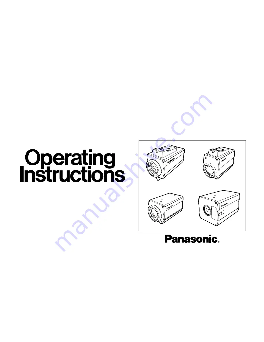
Convertible Camera
AW-E750
AW-E655
AW-E650
AW-E350
Before attempting to connect, operate or adjust this product,
please read these instructions completely.
Page 1: ...Convertible Camera AW E750 AW E655 AW E650 AW E350 Before attempting to connect operate or adjust this product please read these instructions completely AW E350 AW E750 AW E650 AW E655 ...
Page 2: ...indicates safety information FCC Note This device complies with Part 15 of the FCC Rules To assure continued compliance follow the attached installation instructions and do not make any unauthorized modifications This equipment has been tested and found to comply with the limits for a class A digital device pursuant to Part 15 of the FCC Rules These limits are designed to provide reasonable protec...
Page 3: ...S AND THEIR FUNCTIONS 9 MOUNTING 13 FLANGE BACK ADJUSTMENT FOR ZOOM LENS 15 IRIS GAIN CONTROL IN A LENS 17 CONNECTIONS 18 ADJUSTMENT 23 USE MODE SETTING 29 MENU ITEM SETTING 31 SETTING AND CHANGING THE OPTIONAL CARDS 54 SETTING TO INITIAL SET 56 APPEARANCE 60 SPECIFICATIONS 64 STANDARD ACCESSORIES 68 ...
Page 4: ...ly performed by following the setup menu Connection to peripheral devices such as a RCU a RCB and a lens and the camera pan tilt unit enables a wide variation of system configurations PREFACE Option cards may also be installed The following cards are not available for AW E750 AW E655 AW E650 AW E350 AW PB301 Component Studio Card AW PB302 RGB Card The camera unit contains this function AW PB303 Hi...
Page 5: ... and AGC FEATURES 8 CCD readout is switchable between field and frame modes Vertical resolution can be stepped up in frame mode and it is effective for shooting still objects 9 The built in synchronized scanning system reduces noise in computer graphics 10 Various correction circuits permit video reproduction with high fidelity 11 Chroma detail correction enables clear shots of dark color objects ...
Page 6: ... may result in a smeared picture unique to the CCD The ATW function under fluorescent illumination can adversely change the white balance SPECIAL NOTES ON OPERATION There is a cooling fan inside Do not cover the port or otherwise block ventilation during operation Internal heat buildup can cause a fire It is an expendable part and must be replaced about every 30 000 hours Whenever fan replace ment...
Page 7: ...nts when cleaning the camera body Do not aim the camera toward the sun no matter whether it is turned on or not Do not expose the camera or Remote Control Unit RCU to rain or moisture and do not try to operate the equipment in wet conditions Do not operate the camera or RCU if it becomes wet Do not operate the camera or Remote Control Unit RCU outdoors during a lightning storm Do not use the camer...
Page 8: ...er any servicing to qualified service personnel Handle the camera with care Protect the precision made lens by placing the lens cap over when the camera is not in use If the lens is not installed protect the surface of the prism by placing the body cap into the lens mount hole Use a mild blower or lens cleaning tissue designed for coated lenses to clean the surface of the lens or prism in the even...
Page 9: ... 9 MAJOR OPERATING CONTROLS AND THEIR FUNCTIONS r t q w e y Front View Top View Side View model AW E655 only ...
Page 10: ...nting hole To install the camera on a wall or ceiling or to use a pan tilt head or tripod secure the unit using this screw hole 1 4 20UNC or using the accessory mounting adaptor 5 Cooling Fan models AW E750 AW E655 only The cooling fan can be set to Auto or OFF on the menu 6 Expansion Slot Remove the cover and connect the expansion card box 7 8 9 A C B 1 Lens Mount 2 3 Standard bayonet type B4 mou...
Page 11: ...essing this switch while the Sub Menu is on the screen While the Sub Menu is displayed any setting can be brought down to a lower value with this switch When the menu is not displayed or the camera is in shooting mode the color bar and the shooting conditions are indicated by pressing the switch 11 Video Output Connector VIDEO OUT A composite video signal is provided at this con nector 12 Iris Con...
Page 12: ...nce signal BB 18 Cable Clamp Clamp the DC Power Supply Cable AW CA4T1 connected to the DC 12 V Input Connector to pre vent it from slipping out 19 Optional Card Slot Slot for inserting an optional card For details refer to the manual for optional cards 15 Power Indicator Red LED lamp lights to indicate that the specified DC power is supplied to the camera 16 DC 12 V Input Connector DC 12V IN 12 V ...
Page 13: ...ns can be used Be absolutely sure that a lens whose mount threads extend no more than 4 3 mm from the lens mount surface is used Use of any other kind of lens may damage the camera unit Some lenses need to be attached in a different way Therefore reference should also be made to the operating instructions that accompany the lens Remove the lens mount cap align the lens with the thread ridges on th...
Page 14: ...ra Use a screwdriver or similar to tighten the screws to secure the mounting adaptor Make sure that the mounting adaptor is attached the right way round Preventing the camera from falling or coming off OWhen attaching a camera to the pan tilt head AW PH300A AW PH350 follow the directions in the Operating Instructions to fix the camera firmly in position In addition link the camera to the pan tilt ...
Page 15: ...amera 4 Set the lens to its TELE end first and adjust its focus with the focus ring 5 Set the lens to its widest angle next and adjust its focus with the flange back adjust ring 6 Adjust the focus ring and the flange back adjust ring alternately for the best focus within the zooming range Tighten the flange back lock knob upon completion of focusing 7 Turn the iris selection switch to Position A 3...
Page 16: ... object 2 Aim the camera at any object over 2 meters away from the camera remove the cap over the camera s flange back adjust screw and loosen the LOCK screw 3 Set the lens to its TELE end first and adjust its focus with the focus ring 4 Set the lens to its widest angle next and turn the FOCUS screw to adjust its focus 5 Adjust the focus ring and FOCUS screw alternately for the best focus within t...
Page 17: ...riv er through the hole may be done as follows Shape and location of the hole may vary depending on the type of lens 1 Turn the iris selection switch to Position A AUTO 2 Rotate the iris gain control to the maximum gain but in a range where no hunting or oscillating of the iris ring develops Iris gain control G S Automatic iris power zoom lens ...
Page 18: ...ONNECTOR Connection to any device which has a composite input connector such as a video monitor or a VTR must be made through the VIDEO OUT Connector Power supply to the camera must be through the optional DC power supply Cable AW CA4T1 For DC power supply use the optional AC adaptor AW PS505 O I FUSE FUSE VIDEO OUT Connector Video monitor AC Adaptor AW PS505 VIDEO IN 75 Ω coaxial cable DC Power s...
Page 19: ...ween the camera and WV RC550 is 100 m Use the following options for cable extension Studio Cable WV CA26U15 15 m 50 ft WV CA26U30 30 m 100 ft WV CA26U100 100 m 330 ft Cable Joint Adaptor WV CA26T26 CONNECTION OF A REMOTE CONTROL UNIT RCU GEN LOCK GEN LOCK IN AUX AUX IN AUTO AUTO 75Ω Hi Z Hi Z AUTO AUTO 75 Ω Hi Z Hi Z R PR C R PR C OUT OUT OUT OUT AUDIO AUDIO SEE MANUAL SEE MANUAL VIDEO 1 VIDEO 1 G...
Page 20: ...on trolled remotely by the RCB Notes The monitor output signals of the RCB attenuate and deteriorate with cable length It is recommend ed that the signals from the monitor output be used for monitoring purposes only No gen lock signal is available from the RCB If a longer distance more than 3 m is desired between the camera and the RCB use the following optional cable AW CA50B10 and WV CA10B02 2 m...
Page 21: ... the camera used for supplying the reference signals Adjust the SC phase and H phase at the Video Output Connector 30 10 m 5 3 2 1 5 0 II 15 10 7 5 1 5 5 10 20 40 77 30 10 m 5 3 2 1 5 0 II 15 10 7 5 1 5 5 10 20 40 77 30 10 m 5 3 2 1 5 0 II 15 10 7 5 1 5 5 10 20 40 77 VIDEO OUT CAMERA Camera for External Sync or Special Effect Generator G L IN VIDEO OUT OUTPUT INPUT Video Output To Special Effect G...
Page 22: ... the software used to control the camera O I FUSE FUSE DC Power Cable AW CA4T1 Computer VIDEO OUT Connector AC ADAPTOR AW PS505 75 Ω Coaxial Cable Composite Video Input Connector VIDEO IN Video Monitor RS 232C PC Control Cable AW CA50T9 10m CONNECTION OF DEVICES WITH CAMERA PAN TILT CONTROL SYSTEM Refer to the operating instructions of the pan tilt head to connect camera to it ...
Page 23: ...lection switch to either AWC A or AWC B of RCU or select the white balance mode either AWC A or AWC B by menu 2 Aim the camera at a white object a white wall or a white handkerchief and zoom in to enlarge the image as much as possible ADJUSTMENT by CAMERA 3 In normal shooting mode Press the ITEM AWC switch for over 2 second ADJUSTMENT with the RCU RCB Hybrid control panel 4 When the AUTO set switc...
Page 24: ... 10 of the monitor screen area AUTOMATIC TRACKING WHITE BALANCE SETTING ATW White balance will be automatically set to continuously match changes of light source and color temperature while the white balance setting is set to ATW Notes ATW might not function properly when high bright ness light ex fluorescent lamp beams into a screen White balance may not be accurately set if there is no white obj...
Page 25: ...inting setting in only USER MODE ADJUSTMENT by CAMERA Press the YES ABC switch for over 2 seconds and the black balance will be set automatically in 10 seconds Minimize the carrier wave using the red blue gain controls Waveform for white balance set chart In user mode black balance fine adjustment can be performed with the red pedestal blue pedestal setting after setting the black balance ADJUSTME...
Page 26: ...stal in the Iris Shutter Gain Set sub menu in USER MODE 3 Set the pedestal level to 5 IRE 0 035 V with the YES ABC switch or the NO BAR switch ADJUSTMENT with RCU RCB Hybrid control panel Adjust the pedestal level to 5 IRE with the total pedestal adjustment NO BAR Switch YES ABC Switch 5 IRE 0 035 V TOTAL PEDESTAL Brightness Set Picture Level 0 Light PEAK AVG 0 Light Area Top Cut Auto ND ELC OFF A...
Page 27: ...the camera or the RCU RCB when external synchronizing signals are supplied to the system in cases where multiple cameras are used or peripheral devices are connected HORIZONTAL PHASE CONTROL Observe the waveform of the external synchronizing input signal black burst signal and video output signal on a two channel oscilloscope Then match the horizon tal phase of both signals by adjusting them with ...
Page 28: ...stment with the YES ABC switch and the NO BAR switch CAUTION When horizontal phase adjustment is required using RCU RCB or Hybrid Control Panel BAR CAM switch should be set to BAR Horizontal phase cannot be adjusted if the switch is in the CAM position After adjustment set BAR CAM switch back to CAM CAUTION When color phase adjustment is required using RCU RCB or Hybrid Control Panel BAR CAM switc...
Page 29: ...ings can be changed using a detail menu SETTING BY CAMERA 1 Turn the camera on while keeping the MENU switch depressed The use mode setting menu shown at right appears on the monitor screen and one of the use mode blinks 2 Press the MENU switch ITEM AWC switch or NO BAR switch to let the desired use mode blink MENU switch A The blinking item moves up by one ITEM AWC switch S NO BAR switch The blin...
Page 30: ...the posi tion of the scene file switch Halogen Mode Fluorescent Mode Outdoor Mode User s Mode Scene File Switch Position of RCU RCB 1 2 3 USER SET Scene File Switch Position of Hybrid control panel 1 2 3 4 CAMERA RCU RCB Hybrid Control Panel ITEM AWC YES ABC NO BAR MENU SCENE FILE Switch SCENE FILE Switch ...
Page 31: ...et Color Set G L Color Bar Set Sharpness DTL Set Other Set Option Card Set Initialize Data End User Mode Set Iris Shutter Gain Set Color Set G L Color Bar Set Detail Set1 Detail Set2 Color Matrix Set Other Set1 Other Set2 Option Card Set Initialize Data End Main Menu of Halogen Fluorescent Outdoor Mode Main Menu of User Mode Use Mode Blinking Notes Composite signals are output from the video outpu...
Page 32: ...s on the screen 4 Select the desired item to be changed in its settings using the the MENU switch A and ITEM AWC switch S 5 Press the YES ABC switch or NO BAR switch to change the settings 6 Select Return using the MENU switch and ITEM AWC switch then press the YES ABC switch to return to the main menu 7 After changing the settings take the following steps Camera alone Select End using the MENU sw...
Page 33: ...White Bal AWC A ATW Speed Nega Posi Posi Return G L Adjustment Set H Phase 0 SC Coarse 1 SC Fine 0 Color Bar Set 7 5IRE Return Sharpness DTL Set DTL Select Sharpness Level High Noise Suppress OFF Clean DNR OFF 3D DNR OFF DTL Flesh Tone Mid Return Other Set Contrast Gamma Mid Shutter Speed OFF Synchro Scan V Resolution Normal Baud Rate 9600bps Component Y Pr Pb Digital Extender OFF Fan Auto Auto Fo...
Page 34: ...Center Top cut BTM cut R L cut A photometric measurement method can be selected for AUTO IRIS AUTO GAIN UP AUTO ND ELC All All the screen area is measured Center The screen is measured mainly in the center area about one third of both the top and bottom and one third of both the right and left portions of the screen are excluded from measurement Top cut About one third of the top part of the scree...
Page 35: ...W E350 Manual setting is possible only when the Auto Gain Up control 1 5 is in the OFF position 0 dB 0 dB should be selected in normal cases 1 dB to 30 dB Use this range if sufficient video out put cannot be obtained even when the lens iris is opened in shooting dark scenes AW E750 AW E655 AW E650 Night Eye L Use this setting if it is not possible to achieve a satisfactory video output even at 30 ...
Page 36: ...g 5 2 go OFF and cannot be changed If the images CCD read out mode setting 5 4 have been set to Fine 1 15s to 2s is selected as the storage time setting and the sensitivity is set to about one half of that obtained with when they have been set to Normal 36 Only 0 dB 9 dB or 18 dB can be selected in case of using the RCU RCB 0 dB when the manual GAIN switch on the hybrid control panel is at LOW 9 d...
Page 37: ...ht AWC A AWC B Once the white balance is adjusted with the ITEM AWC switch on the back of the camera it is no longer necessary to set the white balance again if you simply select AWC A or AWC B provided that the camera is used under the same conditions Fine color adjustment can be made after setting AWC by red blue gain adjustment in user mode or from the RCU RCB P SET 3 200K The white balance is ...
Page 38: ...e adjustment of subcarrier phase can be made when a genlock signal is supplied 4 Color Bar Setup Setting Color Bar Set 0 0 IRE 7 5 IRE The setup level of color bar can be adjusted 4 ATW Speed Setting ATW Speed SLOW 2 SLOW 1 MID FAST 1 FAST 2 ATW Speed can be set 5 Negative Positive Selection Nega Posi Posi Nega Posi Normal image Nega Image is shown reversed in darkness and color Neither P SET 3 20...
Page 39: ... standard setting HIGH The outline compensation for the flesh tones is accentuated 2 Detail Level Setting Level OFF LOW HIGH Detail level can be adjusted when Detail Select set ting is at Normal Super DTL level can be adjusted when it is at Super DTL In case of using the RCU RCB the above can be adjusted with the contour correction switch DTL 4 Sharpness DTL Set Display 1 Detail Select Setting DTL...
Page 40: ... the table below In case of using the RCU RCB none of the shutter speeds 1 250 1 2 000 1 4 000 and 1 10 000 can be selected In case of using the hybrid control panel only OFF 1 100 or Auto ND ELC can be selected If the lens iris switch is at M Manual when oper ating the camera alone or when the iris switch on the RCU RCB is at AUTO Auto ND may not function Set the lens iris switch to A Auto Flicke...
Page 41: ...her such environment Auto The temperature is detected automatically and the fan starts operating when the temperature exceeds approx 10 C in the storage mode or approx 35 C in any other mode Under normal circumstances the Auto setting is used 9 Auto Focus Setting Auto Focus OFF ON model AW E655 only This enables auto focus ON and OFF to be controlled when the zoom focus cable of a Canon AF lens ha...
Page 42: ... 0 Color Bar Set 7 5IRE Return Detail Set1 Detail High H Detail Level H 11 V Detail Level H 6 H Detail Level L 7 V Detail Level L 3 Detail Band 2 Noise Suppress 3 Level Dependent 0 Dark Detail 0 Return Detail Set2 Chroma Detail 0 Flesh DTL Level Mid Corner Detail OFF Precision Detail OFF Return Settings enclosed in parentheses can be set with the RCU RCB switch or VR in RCU RCB mode To return to t...
Page 43: ...y Gain 0 G_Cy Phase 0 Cy Gain 0 Cy Phase 0 Cy_B Gain 0 Cy_B Phase 0 B Gain 0 B Phase 0 Return Other Set1 Gamma 0 45 Knee Point 98 White Clip 110 Flare R 0 Flare G 0 Flare B 0 Black Stretch OFF Clean DNR OFF 3D DNR OFF 2D LPF OFF Return Other Set2 Field Frame Field Baud Rate 9600bps Component Y Pr Pb Digital Extender OFF Fan Auto Auto Focus OFF Filter Normal Return Color Matrix Set Display Other Se...
Page 44: ...0 to A50 The ratio of AUTO IRIS AGC ELC detected peak to average can be adjusted within a range 3 Photometric Measurement Method Setting Light Area All Center Top cut BTM cut R L cut A photometric measurement method can be selected for AUTO IRIS AGC ELC All All the screen area is measured Center The screen is measured mainly in the center area about one third of both the top and bottom and one thi...
Page 45: ...een selected as the electronic shutter mode setting 6 5 When the screen of a work station etc is to be shot the noise on the horizontal bars can be reduced by proceeding with the synchro scan adjustment Refer to the table below for the light quantity set tings to be used in each shutter mode and during synchro scanning If Frame 1 is selected in CCD Read Out Mode Setting 9 Electronic Shutter Mode S...
Page 46: ...ossible to achieve a satisfactory video output even at 30 dB N Eye H Night Eye H Use this setting if it is not possible to achieve a satisfactory video output even at the Night Eye L setting AW E350 N Eye Night Eye Use this setting if it is not possi ble to achieve a satisfactory video output even at 30 dB Only 0 dB 9 dB or 18 dB AGC LOW AGC HIGH can be selected in case of using the RCU RCB If the...
Page 47: ...storage time OFF Under normal circumstances this setting is used Auto ALC is performed followed by AGC and then by the data storage and the camera automatical ly adjusts the light quantity If the electronic shutter mode setting 6 5 is set to ELC ELC is performed followed by ALC AGC and then by the data storage in this order and the light quantity is automatically adjusted The electronic shutter mo...
Page 48: ...e is adjusted to 5 600K illumination 3 ATW Speed Setting ATW Speed SLOW 2 SLOW 1 MID FAST 1 FAST 2 ATW Speed can be set 4 Black Level Setting Pedestal 150 to 150 The black level pedestal of the luminance Y signal can be set Used in adjusting the black levels of two or more cameras 5 Painting Setting Painting R Gain B Gain R Pedestal B Pedestal 150 to 150 R Gain B Gain Fine adjustment of the white ...
Page 49: ... 9 Detail Set Display 1 Detail Level Setting Detail OFF Low High Contour correction quantity can be selected Detail settings made using the Horizontal Vertical Detail Level HIGH LOW Setting 2 Horizontal Detail Level HIGH Setting H Detail Level H L 1 to 63 3 Vertical Detail Level HIGH Setting V Detail Level H L 1 to 31 4 Horizontal Detail Level LOW Setting H Detail Level L 0 to H 1 5 Vertical Detai...
Page 50: ...f the darker portions of an object can be emphasized This setting is possible only when the Level Dependent Compensation Level Setting 9 9 is set to 0 10 Chroma Detail Compensation Level Setting Chroma Detail 0 to 15 The contours of high hue portions of an object can be emphasized 11 Flesh DTL Level Setting Flesh DTL Level Low Mid High LOW The roughness of the flesh tones is minimized MID This is ...
Page 51: ...ncreases or decreases the intermedi ate color of yellow Yl Phase Varies the hue of the yellow Yl_G Gain Increases or decreases the intermedi ate color between yellow and green Yl_G Phase Varies the hue of the intermediate color between yellow and green G Gain Increases or decreases the green G Phase Varies the hue of the green G_Cy Gain Increases or decreases the intermedi ate color between green ...
Page 52: ... suppression of black portions at low luminance can be set to ON or OFF 6 Clean DNR Setting Clean DNR HIGH LOW OFF This enables the clean DNR effect to be selected 7 3D DNR Setting 3D DNR OFF Low Mid High This enables the 3D DNR effect to be selected When Mid or High is selected the noise is reduced but lag increases 8 2 dimensional Lowpass Filter Setting 2D LPF OFF LOW HIGH The 2D lowpass filter ...
Page 53: ...gm even at the 1 16ND setting 11 Component Output Setting Component RGB Y Pr Pb Y C This enables RGB Y Pr Pb or Y C to be selected as the component signals which are to be output from the I F REMOTE connector 12 Digital Extender Setting Digital Extender OFF ON OFF Under normal circumstances this setting is used ON An extender effect which is approximately 1 5 times greater is achieved However the ...
Page 54: ...50 1 Zebra Indicator Setting Zebra Indicator ON OFF This is used to select whether to display the zebra pattern on the viewfinder ON The zebra pattern is displayed on the viewfinder OFF The zebra pattern is not displayed on the viewfinder If CVBS is selected as the EVF output setting 4 the zebra pattern will not be displayed on the viewfinder even when ON has been set for the zebra pattern display...
Page 55: ...positions and as such they may be at vari ance with their optical positions 4 EVF Output Setting EVF Output Y CVBS This is used to set the signals to be output to the viewfinder Y The luminance signal is output to the viewfinder CVBS The color signals are output to the viewfinder When CVBS has been selected as the setting the zebra pattern will not be displayed on the viewfinder 5 Auto Focus Auto ...
Page 56: ...ngs 1 2 3 Initialize Data Halogen Mode Do you want to initialize Halogen Mode settings O K YES SW Cancel NO SW Halogen Mode Initialized Halogen Mode Unchanged are initialized the screen shown at 2 and the cam era returns to main menu 3 If the NO BAR switch is pressed or if the YES ABC switch is not pressed within about 10 seconds the screen shown at 3 and the camera returns to main menu and the ex...
Page 57: ... OFF OFF OFF Mid 0 0 Top cut ON ON N Eye H 1 N Eye 2 OFF 40 Outdoor mode 0 0 AWC A Posi 0 1 0 7 5 IRE Sharpness High OFF OFF OFF Mid 0 0 Top cut OFF OFF 0dB 0dB OFF 0 Fluorescent mode 0 0 AWC A Posi 0 1 0 7 5 IRE Sharpness High OFF OFF OFF Mid 0 0 Top cut OFF OFF 0dB 0dB OFF 0 Halogen mode Chroma Level Flesh Tone White Bal ATW Speed Nega Posi H Phase SC Coarse SC Fine Color Bar Set DTL Select Leve...
Page 58: ...t Digital Extender Fan Auto Focus Filter Mid Auto ND Normal 9 600bps Y Pr Pb OFF Auto OFF Normal Mid OFF Normal 9 600bps Y Pr Pb OFF Auto OFF Normal Mid OFF Normal 9 600bps Y Pr Pb OFF Auto OFF Normal Halogen Fluorescent Outdoor Mode Chroma Level White Bal ATW Speed Pedestal Painting R Gain B Gain R Pedestal B Pedestal Nega Posi Color Set 2 AWC A Mid 0 0 0 0 0 Posi Item User mode H Phase SC Coarse...
Page 59: ...il Flesh DTL Level Corner Detail Precision Detail Detail Set 2 0 Mid OFF OFF B_Mg Gain B_Mg Phase Mg Gain Mg Phase Mg_R Gain Mg_R Phase R Gain R Phase Color Matrix Set 1 0 0 27 0 0 0 15 0 R_Yl Gain R_Yl Phase Yl Gain Yl Phase Yl_G Gain Yl_G Phase G Gain G Phase Color Matrix Set 2 0 0 18 6 0 0 30 112 G_Cy Gain G_Cy Phase Cy Gain Cy Phase Cy_B Gain Cy_B Phase B Gain B Phase Color Matrix Set 3 0 0 44...
Page 60: ...W E750 APPEARANCE Unit inch mm Convertible Camera AW MENU OPTION CARD VIDEO OUT I F REMOTE G LIN IRIS DC12V IN ITEM AWC YES ABC NO BAR 6 11 16 170 15 32 12 25 64 10 3 5 16 84 11 16 18 3 1 32 77 Unit inch mm ...
Page 61: ... 61 Convertible Camera AW MENU OPTION CARD VIDEO OUT ZOOM FOCUS I F REMOTE G LIN IRIS DC12V IN ITEM AWC YES ABC NO BAR MIC 15 32 12 25 64 10 6 5 16 160 3 5 16 84 3 3 4 96 11 16 18 Unit inch mm AW E655 ...
Page 62: ... 62 Convertible Camera AW MENU OPTION CARD VIDEO OUT I F REMOTE G LIN IRIS DC12V IN ITEM AWC YES ABC NO BAR 15 32 12 25 64 10 6 1 8 155 3 5 16 84 3 1 32 77 Unit inch mm AW E650 ...
Page 63: ... 63 AW E350 FOCUS LOCK Convertible Camera AW MENU OPTION CARD VIDEO OUT I F REMOTE G LIN IRIS DC12V IN ITEM AWC YES ABC NO BAR 5 11 16 145 3 64 1 25 64 10 3 5 16 84 3 1 32 77 Unit inch mm ...
Page 64: ...p p 75 ohms C 0 286 Vp p 75 ohms burst D sub 50P x 1 Y Pr Pb Y 1 Vp p 75 ohms Pr Pb 0 7 Vp p 75 ohms D sub 50P x 1 RGB G 1 Vp p 75 ohms RB 0 7 Vp p 75 ohms D sub 50P x 1 Standard illumination 2 000 lx F14 3 200K color temperature Minimum illumination 0 00005 lx at F1 4 Night Eye mode 30 dB digital gain 2s storage time output of 70 or above S N ratio 67 dB Y signal DTL OFF DNR ON Horizontal resolut...
Page 65: ... screen is not displayed VIDEO OUT BNC connector VIDEO OUT BNC connector G L IN BNC connector G L IN BNC connector Input output connectors IRIS 12P round connector IRIS 12P round connector DC 12V IN DC connector DC 12V IN DC connector I F REMOTE 50P D sub connector I F REMOTE 50P D sub connector ZOOM FOCUS 12P round connector Indicator Red LED power ON when lighted For storage 20 C to 60 C Allowab...
Page 66: ...ohms D sub 50P x 1 RGB G 1 Vp p 75 ohms RB 0 7 Vp p 75 ohms D sub 50P x 1 Standard illumination 2 000 lx 2 000 lx color temperature F14 3 200K F9 5 3 200K 0 00005 lx at F1 4 0 00015 lx at F1 4 Minimum illumination Night Eye mode 30 dB digital gain Night Eye mode 30 dB digital gain 2s storage time output of 70 or above 2s storage time output of 70 or above S N ratio 67 dB Y signal DTL OFF DNR ON 66...
Page 67: ...witches ITEM AWC S AWC when menu screen is not displayed UP ABC ABC when menu screen is not displayed NO BAR BAR when menu screen is not displayed VIDEO OUT BNC connector G L IN BNC connector Input output connectors IRIS 12P round connector DC 12V IN DC connector I F REMOTE 50P D sub connector Indicator Red LED power ON when lighted For storage 20 C to 60 C Allowable temperature ranges For guarant...
Page 68: ...Rubber Sheet 1 Mounting Adaptor 1 Screw 2 STANDARD ACCESSORIES Mounting Spacer models AW E750 AW E655 only 1 68 ...
Page 69: ......
Page 70: ......
Page 71: ......
Page 72: ...ernment Marketing Department 52 West Gude Drive Rockville MD 20850 301 738 3840 Broadcast PARTS INFORMATION ORDERING 9 00 a m 5 00 p m EST 800 334 4881 24 Hr Fax 800 334 4880 Emergency after hour parts orders 800 334 4881 TECHNICAL SUPPORT Emergency 24 Hour Service 800 222 0741 Panasonic Canada Inc 5770 Ambler Drive Mississauga Ontario L4W 2T3 905 624 5010 Panasonic de Mexico S A de C V Av angel U...