
AVM3
P
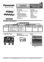
PRODUCT TYPES
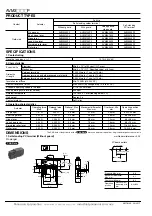
SPECIFICATIONS
1. Contact rating
2. Characteristics
3. Operating characteristics
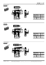
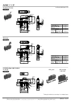
DIMENSIONS
Contact
Actuator
Part No.
Self-standing solder terminal
Self-standing
PC terminal
Without guard
With guard
With opposite
side guard
Gold-clad
Pin plunger
AVM3205P9
AVM3105P9
AVM3305P9
AVM3405P9
Short hinge lever
AVM3215P9
AVM3115P9
AVM3315P9
AVM3415P9
Hinge lever
AVM3225P9
AVM3125P9
AVM3325P9
AVM3425P9
Long hinge lever
AVM3235P9
AVM3135P9
AVM3335P9
AVM3435P9
Simulated roller lever
AVM3245P9
AVM3145P9
AVM3345P9
AVM3445P9
Roller lever
AVM3255P9
AVM3155P9
AVM3355P9
AVM3455P9
Resistive load (cos
φ
]
1)
10.1A, 250V AC
Expected life
Electrical
Min. 5
×
10
4
(at 20 cpm) (O.T. max.)
Mechanical
Min. 3
×
10
7
(O.T.: Specified value), at 60 cpm
Dielectric
strength
Between terminals
1,000 Vrms for 1 min. (at 10 mA)
Between terminals and other exposed metal parts
2,000 Vrms for 1 min. (at 10 mA)
Between terminals and ground
2,000 Vrms for 1 min. (at 10 mA)
Insulation resistance
Min. 100M
Ω
(at 500V DC)
Contact resistance (initial)
Max. 50m
Ω
(By voltage drop, 1A 6 to 8V DC)
Allowable operating speed (at no load)
0.1 to 1,000 mm/sec.
Max. operating cycle rate (at no load)
300 cpm
Ambient temperature
–25 to +85
°
C (Not freezing below 0
°
C)
Unit weight
Approx. 2g
Contact material
AgNi alloy
Actuator
Operating force,
Max.
Release force,
Min.
Pretravel, Max.
mm
Movement differential,
Max. mm
Overtravel, Min.
mm
Operating position
mm
Pin plunger
1.47 N
0.20 N
0.6 mm
0.1 mm
0.4 mm
8.4
±
0.25 mm
Short hinge lever
0.59 N
0.039 N
2.5 mm
0.5 mm
0.8 mm
8.8
±
0.8 mm
Hinge lever
0.54 N
0.034 N
2.8 mm
0.8 mm
1.2 mm
8.8
±
0.8 mm
Long hinge lever
0.44 N
0.029 N
3.5 mm
1.0 mm
1.6 mm
8.8
±
1.2 mm
Simulated roller lever
0.54 N
0.034 N
2.8 mm
0.8 mm
1.2 mm
11.65
±
0.8 mm
Roller lever
0.59 N
0.039 N
2.5 mm
0.5 mm
0.8 mm
14.5
±
0.8 mm
mm General tolerance:
±
0.25
1. Self-standing PC terminal (Without guard)
Pin plunger
2.2
NO
NC
C
0.5
0.6 max.
8.7
15.4
0.9
7.4
0.75
9.5
1.8
6.4
5.2
1.25
0.5
4.0
(P.T.)
7.7
-0.05
+0.1
2.4
2.4
19.8
2.5
7.6
±
0.3
±
0.1
±
0.15
±
0.15
±
0.3
±
0.1
2.2
±
0.1
±
0.15
3.4
±
0.1
±
0.2
1.1
±
0.12
1.5
±
0.12
1.85
±
0.2
6.7 8.4
±
0.25
(O.P.)
11.8
(O.P.)
±
0.35
2.4
dia.
+0.1
-0.05
PC board pattern
8.7
±
0.15
15.4
±
0.1
Pin plunger position
(10.55)
3-1.2
dia.
±
0.05
Pretravel, Max. mm
0.6
Movement differential,
Max. mm
0.1
Overtravel, Min mm
0.4
Operating
position
Distance from
mounting hole,
mm
8.4
±
0.25
CAD Data
AECTB12E 201201-T
Panasonic Corporation
Automation Controls Business Unit
industrial.panasonic.com/ac/e
The CAD data of the products with a
CAD Data
mark can be downloaded from: http://industrial.panasonic.com/ac/e


