background image

6

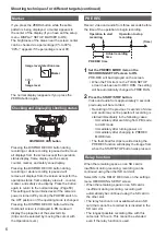
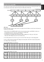
Marker

If you press the ZEBRA button while the zebra 
pattern is being displayed, a marker appears in 
the center of the display (if you have set the setup 
menu, DISPLAY SETUP, MARKER to ON). 
The brightness of the areas near the screen center 
can be checked as a percentage (0% to 99%).
“99%↑” appears if the percentage is over 99.

99%

Image level detection area

Image level

Marker

The normal display reappears if you press the 
ZEBRA button again.

Checking and displaying shooting status

MENU

START/

STOP 2

PUSH-ENTER

MODE

POWER

DISP/

MODE CHK

USER 1

USER 2

FUNCTION

FOCUS

IRIS GAIN WHITE BAL

B

PUSH AUTO

MEGA

ON

OFF

O.I.S.

CAM

ON

CH1

CH2

AUDIO LEVEL

..

OFF

PB

+

AUDIO MON

EXEC

A

PRST

L

M

H

A

M

DISP/MODE CHK button

Pressing the DISP/MODE CHK button during 
recording or while recording is paused will remove 
all displays from the screen except the operation 
status display, frame display (such as area), 
counter, marker, and safety zone display.
Pressing the DISP/MODE CHK button during 
recording or while recording is paused will 
remove all displays from the screen except for the 
operation status, frame display erea etc., counter, 
marker, and safety zone display. Press the button 
again to return to the normal display. (Page 50)
This setting will be maintained even if the camera’s 
power is turned off by moving the POWER switch to 
the OFF position or if the operating mode is changed.
Pressing the DISP/MODE CHK button while the 
thumbnail screen is displayed in PB mode will 
display the properties of the selected clip. 
(Clips can be selected by moving the cursor with 
the Operation lever.)

Shooting techniques for different targets (continued)

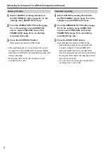
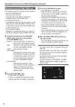
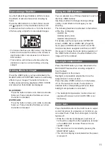
PRE REC

Record video and audio from three seconds before 
the time of the operation to begin recording.

Operation to start 

recording

Operation to stop 

recording

Actual recording 

time

PRE REC time

(Time)

1

  Set the PREREC MODE item on the 

RECORDING SETUP screen to ON.

PRE-REC will be displayed on the screen.

When the TCG item on the TC/UB SETUP 

• 

screen has been set to REC RUN, the setting 
will be automatically changed to FREE RUN.

2

  Press the START/STOP button.

Video and audio from approximately 3 seconds 
previously will be recorded.

Recording of the previous 3 seconds of video 

• 

and audio may not be possible if recording is 
started immediately in the following cases.

Immediately after switching from PB mode 


ā

to CAM mode
Immediately after turning power on


ā

Immediately after changing to PREREC 


ā

MODE item

The thumbnail for clips recorded using the 

• 

PREREC function will display the image from 
when the START/STOP button was pressed.

Relay function

When the remaining space on an SD card is 
insufficient during recording, recording can be 
continued using the other SD card slot.
Select ON in the RELAY REC item on the settings 
menu RECORDING SETUP screen.

When the remaining space on an SD card is 

• 

insufficient during recording, recording will 
automatically be continued using the SD card in 
the other slot.
The relay function is not available when an SD 

• 

card that cannot be recorded to is inserted in the 
SD card slot.
The longest possible recording time with this 

• 

camera is 12 hours. This cannot be extended 
even if the relay function is used.

Summary of Contents for AVCCAM AG-AF100P

Page 1: ...or future use ENGLISH Volume 2 Note that Operation Instructions Vol 2 describes advanced operations of the Memory Card Camera Recorder For instructions on basic operations of the Memory Card Camera Recorder refer to Operating Instructions Vol 1 printed documents contained in the supplied CD ROM Vol 2 This product is eligible for the AVCCAM 3 Year Warranty Repair Program For details see page 5 of v...

Page 2: ...ophone and audio equipment 17 Adjusting the recording level 18 Using scene files 19 Changing scene file settings 19 Saving scene files and other settings on SD Memory Cards 21 Clip metadata 22 Uploading the metadata META DATA 23 Selecting the USER CLIP NAME recording method 23 Using the Counter 24 Counter display 24 TC preset mode 24 Volume 1 Read this first IMPORTANT SAFETY INSTRUCTIONS Recommend...

Page 3: ...layback functions 39 Fast forward rewind 39 Next previous clip 39 Frame by frame playback 40 Adjust volume 40 Viewing images on a television 40 Checking the date and time 40 Editing Connecting external units 41 Headphones 41 External microphone 41 Computer non linear editing file transfer 42 TV Monitor 42 Nonlinear editing 44 Displays Screen displays 45 Regular displays 45 Main warning displays 48...

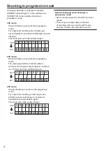
Page 4: ...eo signal will be recorded natively However the external output signal is converted to a 2 3 format 60 fps interlaced signal A B C D E F G H AoAeBoBeBoCeCoDeDoDeEoEeFoFeFoGe GoHeHo He 24 P 60 i 25P mode Shoots 25 frames a second in the progressive mode For output and recording of video signal the 25 frame per second image is converted to 50 field per second interlace signal This mode gives high qu...

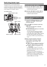
Page 5: ...tor to the normal shooting position Zebra pattern Press the ZEBRA button in the CAM mode to show the zebra pattern or marker on the viewfinder and the LCD monitor so you can check the brightness of the subject Parts that may be whited out through over exposure are shown as a zebra pattern Very bright Reflecting parts POWER FOCUS BARS EVF DTL CH1 SEL INT L ON OFF ON OFF INPUT1 AUDIO MIC POWER 48V I...

Page 6: ...ected clip Clips can be selected by moving the cursor with the Operation lever Shooting techniques for different targets continued PRE REC Record video and audio from three seconds before the time of the operation to begin recording Operation to start recording Operation to stop recording Actual recording time PRE REC time Time 1 Set the PREREC MODE item on the RECORDING SETUP screen to ON PRE REC...

Page 7: ... 1080_30p or 1080_25p VFR shooting does not work in the 720p mode The recording frame rate can be set to any one from the 20 frame rates given in the following table There is a slight a difference between the displayed recording frame rate and the actual recording frame rate Please refer to the table below When SYSTEM FREQ is set to 59 94 Hz Indicated recording frame rate 60 54 48 44 40 36 34 32 3...

Page 8: ...ng setup and during recording During the VFR mode the camera is set to manual focus mode Standard recording 1 Select 1080 30P recording format from the REC FORMAT option page 51 on the settings menu SCENE FILE screen 2 From the OPERATION TYPE option page 51 on the settings menu SCENE FILE screen select FILM CAM and set the FRAME RATE page 51 to an arbitrary recording frame rate 3 Press the START S...

Page 9: ...1080 30P 2 2 Pull down 30 fps 1080 25P 25 fps Undercrank shooting This is a quick motion effect that can be applied to scenes showing the flow of clouds people standing in the middle of crowds and kung fu etc For example a quick motion effect of x2 can be gained if the VFR recording frame rate is set to 12fps when recording with the 24P recording format that specifies the playback frame rate Recor...

Page 10: ...area focus function and area luminance display simultaneous operation of area focus bar function during MENU setting 2 Press the FUNCTION knob A white frame is displayed There is no change in the operation of the camera other than the display of the frame 3 Press the FUNCTION knob again The white frame turns yellow When the frame is yellow the FUNCTION knob function set via the MENU operates in th...

Page 11: ...to each of the three USER buttons Use these buttons to change shooting settings quickly or add effects to the images you are shooting The following features are allocated to the buttons at the time of shipping USER1 FA USER2 ATW LOCK USER3 REC CHECK For details see the setup menus SW MODE screen USER1 SW to USER3 SW Page 55 If you press a USER button to which one of the functions has been assigned...

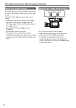
Page 12: ...wave forms are displayed use the viewfinder as well because a part of the recording screen and screen display will be hidden by wave forms Adjusting the volume while shooting MENU START STOP 2 PUSH ENTER MODE POWER DISP MODECHK USER 1 USER 2 FUNCTION FOCUS IRIS GAIN WHITEBAL B PUSHAUTO MEGA ON OFF O I S CAM ON CH1 CH2 AUDIO LEVEL OFF PB AUDIO MON EXEC A PRST L M H A M Adjusting the volume AUDIO MO...

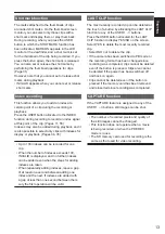
Page 13: ...LID is displayed and no further indexes can be added even when the steps for adding indexes are taken When repeatedly adding indexes leave a gap of at least one second between adding one index and the next If indexes are added with a gap of less than one second between them only the first operation will be valid LAST CLIP function The most recently recorded clip can be deleted at the touch of a bu...

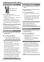
Page 14: ...e to the signal reading system of the imaging element MOS sensor and is not a defect At slow shutter speeds 1 2 to 1 15 white red green or blue dots may appear on the screen However this is not a defect Setting the SYNCRO SCAN 1 Select SYNCRO SCAN from the SHUTTER settings 2 Select the SYNCRO SCAN function with the DIAL SELECT button 3 Turn the SHUTR F RATE dial The SYNCRO SCAN shutter speed can b...

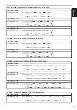
Page 15: ... 1000 1 500 1 250 1080 25P 720 25P Normal OFF 1 50 SYNCRO SCAN 1 25 1 120 1 2000 1 1000 1 500 1 250 1 60 SYSTEM FREQ 59 94Hz OPERATION TYPE VIDEO CAM 1080 60i 720 60P Normal OFF 1 60 SYNCRO SCAN 1 30 1 2000 1 1000 1 500 1 250 1 120 1 100 1 2 1 4 1 8 1 15 1080 30P 720 30P Normal OFF 1 50 SYNCRO SCAN 1 30 1 2000 1 1000 1 500 1 250 1 120 1 60 1 2 1 4 1 8 1 15 1080 24P 720 24P Normal OFF 1 50 SYNCRO S...

Page 16: ...orizontal noise that appears when shooting such subjects By switching to progressive mode you can also shoot PAL system television screens If the set value of the SYNCRO SCAN item of settings menu is displayed in gray it cannot be used with the current recording format This function will only operate for preset values for each recording format as listed below 60i 60P mode 1 60 30P mode 1 30 You ca...

Page 17: ...and audio equipment 1 Connect an external microphone or audio equipment to the INPUT 1 2 XLR 3 pin terminals Page 41 2 Use the INPUT 1 2 switches to switch the audio input LINE audio equipment is connected Input level is 0 dBu MIC an external microphone is connected Input level is 50 dBu You can change the input level to 60 dBu in the setup menus RECORDING SETUP screen MIC GAIN1 and MIC GAIN2 Page...

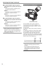
Page 18: ...mately 8 dB higher than Panasonic broadcasting camera recorders AJ series products Switching Audio Input continued 4 Use the CH1 SELECT switch to select the input signal to be recorded to audio channel 1 INT L Audio from the built in microphone Lch is recorded to audio channel 1 INPUT 1 Audio from a device connected to INPUT 1 terminal is recorded to channel 1 INPUT 2 Audio from a device connected...

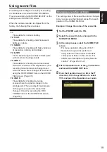
Page 19: ...Page 51 F6 CINE D File suitable for shooting movie like scenes where the dynamic range is to be emphasized The recording format remains unchanged even when the scene file is changed It must be set using the REC FORMAT item on the SCENE FILE screen Page 51 Changing scene file settings The setting value of the scene file can be changed Also you can save the changed scene file to each position of the...

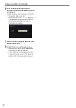
Page 20: ... SET button is pressed when the filename has been set the characters are cleared 7 After you finish setting the filename push the Operation lever 8 Select YES on the confirmation screen Selecting YES will close the NAME EDIT screen and confirm all changes Once confirmed all changed names and values will be saved even if the power is switched off or the scene dial is moved Using scene files continu...

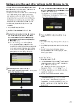
Page 21: ...Card If WRITE NG CANNOT ACCESS appears quit all other operations such as playback before proceeding You can save up to four scene file settings or other settings as files on an SD Memory Card and you can also load them from the card In the case of the scene files the current settings are automatically saved in the unit and the saved data is written on an SD Memory Card When data has been read from...

Page 22: ...DEL NAME Equipment model name AG AF100 for this camera recorder SHOOT This indicates the SHOOTER name of the videographer and the PLACE NAME name of location LOCATION This indicates ALTITUDE LONGITUDE LATITUDE and SOURCE altitude longitude latitude information source Not recorded in this camera recorder SCENARIO 2 This indicates the PROGRAM NAME SCENE NO and TAKE NO NEWS 1 This indicates the REPOR...

Page 23: ...the metadata file name to be loaded they are displayed as RECORD Select this to set whether to record the metadata to be loaded into the unit simultaneously on the SD Memory Card Select ON to record the metadata or OFF to cancel the recording and push the Operation lever The factory setting for this mode is OFF USER CLIP NAME The USER CLIP NAME recording method is selectable Please refer to the ne...

Page 24: ...power MASTER settings 2 Check that the MASTER camera is set to the CAM mode and set the EXT TC LINK item on the setting menu TC UB SETUP screen to MASTER OUTPUTTING LTC SIGNAL is displayed on the screen and the time code is output from the TC PRESET IN OUT terminal VIDEO OUT terminal Select the same REC FORMAT setting for both the MASTER and SLAVE cameras and set the TCG item on the TC UB SETUP sc...

Page 25: ... after recharging the internal battery requires changing Please consult the place of purchase Setting the time code In the setup menus TC UB SETUP screen set the following time code related items Page 57 TC MODE TCG TC PRESET Charging the built in battery Setting the time code Specifying the time code TC PRESET Set TC PRESET so you can record a value of your choice as the initial setting for the t...

Page 26: ...ry Setting the time code continued 4 When the screen below appears set the time code value Tilt the Operation lever in the directions and select time code value Tilt in the direction to move to the next digit and tilt in the directions again to select value You can reset the time code to zero by pressing RESET TC SET button POWER FOCUS BARS EVF DTL CH1 SEL INT L ON OFF ON OFF INPUT1 AUDIO MIC POWE...

Page 27: ...n lever in the direction to move to YES and push the Operation lever 4 Set the user information Tilt the Operation lever in the directions and select user information characters You can use numbers from 0 to 9 and letters from A to F Tilt in the direction to move to the next digit and tilt in the directions again to select character You can reset the user information to nothing by pressing RESET T...

Page 28: ... to move to the next clip ZOOM START STOP PHOTO SHOT EXT DISPLAY DATE TIME VOL PLAY STOP SKIP SKIP MENU ENTER PAUSE SEARCH STILL ADV STILL ADV SEARCH Rewind Press during playback to scroll quickly backwards through the clip at approximately 10 times the speed Repeat the operation to scroll quickly backwards at approximately 20 times the speed Press while paused to move to the previous clip ZOOM ST...

Page 29: ...nail screen Play and delete clips Format SD Memory Card Add or delete index Add or delete shot mark Basic thumbnail screen operations To select thumbnail Tilt the Operation lever in the directions to select thumbnail Orange frame moves To play back clips Select the thumbnail and push the Operation lever For details on playback see page 28 To change the slot for playback Press the SLOT SELECT butto...

Page 30: ...elected clip 9 Time display Page 34 Displays time code at start of clip recording user information at start of clip recording time of recording date of recording date and time of recording according to settings 10 Clip number Displayed in order of recording up to 1000 clips Numbers of clips that cannot be played back e g clips of different recording formats are displayed in red To play clips displ...

Page 31: ...se a shot mark repeat the above steps It is not possible to add shot marks to clips recorded using a consumer camcorder model Select the card slot for playback You can switch the SD memory card slot for playback 1 Press the SLOT SELECT button when the THUMBNAIL screen is displayed in the PB mode 2 Tilt the OPERATION lever in the up down left and right directions to select the SD memory card slot f...

Page 32: ...EC FORMAT item on the settings menu SCENE FILE screen will be restored when the camera is switched to CAM mode If the playback format does not conform to the clips created at the relay destination using the relay recording function thumbnail images will not be displayed will be displayed Thumbnail images will be displayed when the playback format is matched to the clips Repeat playback REPEAT PLAY...

Page 33: ... is selected for playback To turn the resume playback setting off select OFF in step 2 Set skip method SKIP MODE Select which skip cue operation is to be performed when playback is paused 1 Press the MENU button Menu operation Page 44 of Vol 1 2 Select the SKIP MODE item in the PLAY SETUP screen 3 Select skip method CLIP Move to the beginning of the previous or next clip by tilting the Operation l...

Page 34: ... clips with shot marks INDEX Display all clips with indexes Selecting the thumbnail display method THUMBNAIL INDICATOR Set whether or not to display indicator ON OFF Factory default setting is ON Clip protect display and resume playback display will still appear even if this setting is set to OFF DATA DISPLAY Select format of clip time display time code TC user information UB recording time TIME r...

Page 35: ...ke some time to complete depending on the volume of clips to be deleted Deletion cannot be performed via the remote control To abort deletion press the CANCEL button The already deleted clips cannot be restored even if the deletion process is aborted INDEX YES Attach indexes to selected clips 1 Select clip to play and push the Operation lever at the point for an index to be added 2 Select YES on t...

Page 36: ...with scene MARK input Copying clips COPY Copying PICTURE ALL SCENES All scenes SELECT CLIPS Select scenes 6 Select start copy Do not open the SD card slot covers or switch the camera off during copy operations The copy function will not operate if the remaining battery capacity is insufficient Exchange the battery for a charged one or use the AC adaptor Clips recorded with AG 3DA1 cannot be select...

Page 37: ...item and push the Operation lever CARD FORMAT Insert card to be formatted into the camera SD Memory Card will be formatted Proceeding will delete the entire data including videos and picture data from the card Select whether or not to format YES NO and push the Operation lever CARD STATUS Display SD Memory Card information Next page CLIP PROPERTY Display information of selected clip Next page Tilt...

Page 38: ...B User information value at start of recording DATE TIME Date of recording at time at start of recording TIME ZONE Displays time zone DURATION Clip length FORMAT Recording format Clip meta data Press the EXEC button while the clip information screen is being displayed to display more detailed information including video and audio formats and information about the videographer etc Tilt the Operatio...

Page 39: ... direction play or press the PLAY button on the remote control The screen will return to the thumbnail display after the playback of the last clip is completed during fast forward playback The screen will pause at the first clip after the fast rewind playback of the first clip is completed No audio will be played during fast forward or rewind playback Next previous clip 1 Tilt the Operation lever ...

Page 40: ...dphone jack can be adjusted with the AUDIO MON ADV buttons during playback Press the ZOOM VOL buttons if using the remote control Camera or Remote control ZOOM START STOP PHOTO SHOT EXT DISPLAY DATE TIME VOL PLAY STOP SKIP SKIP MENU ENTER PAUSE SEARCH STILL ADV STILL ADV SEARCH MENU START STOP 2 PUSH ENTER AUDIO MON EXEC Viewing images on a television You can view the images on a television if you...

Page 41: ...adaptor When attaching the microphone holder and the microphone holder adaptor be sure to tighten the screws firmly even though you might hear a squeaking sound The microphone holder mounting position is provided at two locations namely in the handle and on top of the INPUT 1 and INPUT 2 terminals If the microphone holder is mounted on the handle the microphone may be captured if a wide angle lens...

Page 42: ... and other factors see page 44 Use a double shielded USB connection cable with a maximum length of three meters TV Monitor Only the output signals from the camera are shown HDMI cable optional BNC cable optional Video cable optional Audio cable optional White CH1 left channel sound Red CH2 right channel sound Connect these cables to the terminals on the television TV Monitor ...

Page 43: ...ltaneously In order to perform simultaneous operation set the SDI OUT on the settings menu AV IN OUT SETUP to OFF When the EVF MODE on the settings menu DISPLAY SETUP is set to AUTO EVF disappears upon opening closing of the LCD No HDMI output is performed when REC FORMAT is set to 1080 24p and SDI 24Ps is set to ON When SDI HDMI OUT SEL is set to DOWNCONV SIDE CROP is disabled in the DOWNCON MODE...

Page 44: ...able disk icon within My Computer or the desktop on the computer screen Page 73 Example Windows Removable disk E Example Macintosh NO NAME When copying files from the camera to a computer be careful to ensure that files are not accidentally overwritten For more details please refer to your computer editing software s operating instructions When changing cards always ensure that the access lamp is ...

Page 45: ...n regarding slot 1 is displayed above and information regarding slot 2 is displayed below Recording possible White Displayed in green if used for recording ā ā Card is write protected Recording not possible Card is full Recording may be possible in some cases ā ā even when this icon is displayed Depending on the memory size and ā ā type of the SD Memory Card used the icon may not be displayed even...

Page 46: ...aximum wide angle Z99 maximum zoom The unit can be switched to mm in the ZOOM FOCUS item of the setting menu DISPLAY SETUP screen The focus position display does not move linearly 15 Focus control information display Displays the focus control information with 99 00 In the auto focus mode AF appears In the manual focus mode MF appears The units can be switched between feet and m in the ZOOM FOCUS ...

Page 47: ...d no card etc Recording in progress during transition to the recording pause mode Recording paused recording standby Warning display 24 Recording function display PRE REC When pre rec mode is ON In interval REC mode 25 Monitor audio level meter When you press the AUDIO MON ADV button the sound volume output from the built in speaker and headphone jack is displayed 26 Safety zone The range of the z...

Page 48: ...other device or personal computer is used for the first time in this camera recorder CHECK CARD is displayed and all operations may be disabled In such a case perform the following 1 Remove the SD memory card from the unit and insert it again Page 38 of Vol 1 The unit recognizes the SD memory card and cancels the CHECK CARD display 2 If the CHECK CARD display is not canceled even after removing an...

Page 49: ... are displayed when an error has occurred in the camera or the SD Memory Card If the problem is not solved by switching the power off and back on again either change the card in accordance with the instructions displayed or consult the place of purchase C CANNOT RECORD Displayed when an error has occurred during recording R REC WARNING Displayed when an error has occurred during recording Start th...

Page 50: ...11 Auto iris control display x 12 Iris display x 13 Zoom position display 14 Focus control information display 15 ND filter display x x 16 Gain display 2 x 17 AWB information display 3 x 18 Marker display 19 Optical Image Stabilizer display x 20 Scene filename display x x 21 Remaining battery capacity display 22 Monitor audio level display Displayed x Not displayed Displayed depending on other set...

Page 51: ... VFR MODE Camera ON Enables the VFR Variable Frame Rate mode OFF Disables the VFR mode Functions only when REC FORMAT is set to 1080 24P 1080 30P or 1080 25P Functions only when OPERATION TYPE FILM CAM Does not function when SDI 24PsF is set to ON Audio cannot be recorded when VFR MODE ON FRAME RATE Camera Sets the FRAME RATE Operates only when OPERATION TYPE FILM CAM You can make the settings fro...

Page 52: ...f the setting the higher the compression level of the high brightness areas The higher the number of the setting the greater the interference in darker areas GAMMA Camera Selects the gamma curves HD NORM This gamma setting is suitable for HD shooting LOW Makes a mellow image using the gamma curve that has a gentle incline in low brightness curve The contrast sharpens SD NORM This is the normal vid...

Page 53: ...cenes from F1 to F6 saved on the SD Memory Card of Slot 2 after selecting the setting values NO Returns to the previous screen CARD WRITE Camera Saves scene files on the SD Memory Card Slot1 Saves the setting values of scene files all scenes from F1 to F6 on the SD Memory Card of Slot 1 Slot2 Saves the setting values of scene files all scenes from F1 to F6 on the SD Memory Card of Slot 2 NO Return...

Page 54: ...n of the GAIN switch When OPERATION TYPE FILM CAM ISO200 ISO250 ISO320 ISO400 ISO500 ISO640 ISO800 ISO1000 ISO1250 ISO1600 ISO2000 ISO2500 ISO3200 When OPERATION TYPE VIDEO CAM 6dB 3dB 0dB 3dB 6dB 9dB 12dB 15dB 18dB ATW Camera Sets the operation of the ATW Auto Tracking White function assigned to the WHITE BAL switch When the ATW function is allocated to the USER button the operation remains effec...

Page 55: ...ing off the camera BACKLIGHT Auto iris control for the backlight compensation SPOTLIGHT Switches auto iris control ON or OFF for the spotlight BLACKFADE Blackfade Page 11 WHITEFADE Whitefade Page 11 USER2 SW Camera PB Assign a function to the USER2 button The setting contents are the same as USER1 ATW LOCK USER3 SW Camera PB Assign a function to the USER3 button The setting contents are the same a...

Page 56: ... for recording has no remaining space recording continues in another SD card if an SD card that can be used for recording is inserted in another SD card slot OFF Relay recording not performed Recording stops when the target SD card has no remaining space PH AUDIO MODE Camera Selects the format of audio recording when REC FORMAT PH LPCM Recording is performed in uncompressed LPCM AC3 Recording is p...

Page 57: ...e rate is set to 24P REC RUN The time code is advanced only when recording TC PRESET Camera Sets the initial time code Set the frame value to 0 or a multiple of 4 when you set recording frame rate of recording format to 24P If any other value is set the recorded time code will mismatch YES NO UB PRESET Camera Sets the user information YES NO EXT TC LINK Camera Synchronizes the initial time code va...

Page 58: ...tially unable to be seen when outputting from the H227A V terminal or SDI OUT terminal during DOWNCONV or the HDMI terminal during DOWNCONV LETTER BOX Letterbox mode Adds black bands at the top and bottom of the image SQUEEZE Squeeze mode Squeezes images horizontally HP MODE Camera Selects the sound heard from the headphones LIVE The sound input from the microphone is output as is This setting is ...

Page 59: ...ER Camera Selects counter operation during recording TOTAL The count continues to increase until the COUNTER RESET button is pressed to reset it CLIP Resets the counter at start of recording and counts the time of each recording session In the PB mode the operation is always in CLIP mode VIDEO OUT OSD Camera PB Select ON to output the information displayed on the screen together with the signals f...

Page 60: ...a PB Adjusts the backlight of the LCD monitor 1 0 1 2 3 1 The backlight becomes brighter 3 The backlight becomes the darkest LCD SET Camera PB Adjusts the display level of images on the LCD monitor BRIGHTNESS COLOR CONTRAST EVF SET Camera PB Adjusts the display level of images on the viewfinder BRIGHTNESS COLOR CONTRAST SELF SHOOT Camera Selects the LCD mirror mode for self portrait shooting Selec...

Page 61: ...on the SD Memory Card Slot1 Reads the user files from the SD Card inserted in Slot 1 Slot2 Reads the user files from the SD Card inserted in Slot 2 NO Returns to the previous screen CARD WRITE Camera PB Saves the user files on the SD Memory Card You can also add a title to the saved files Slot1 Saves the user files on the SD Card inserted in Slot 1 Slot2 Saves the user files on the SD Card inserte...

Page 62: ...tem Display mode Description of settings LENS CHECK Camera ON Checks the communication status with the lens Video shooting is not performed if checking is not proper OFF Does not check the communication status with the lens It is recommended to set LENS CHECK to ON when you are using lenses conforming to the Micro Four Thirds and Four Thirds standard When you are using a lens that has no communica...

Page 63: ...Camera Selects the power saving mode when no operation is performed from the Operation lever MENU button AUDIO MON ADV button USER button or START STOP button for about five minutes when an SD Memory Card has been inserted in the CAM mode ON Power supply to the camera is turned OFF OFF Power supply to the camera is not turned OFF Even when POWER SAVE has been set to ON the power supply does not tu...

Page 64: ...playback format When SYSTEM FREQ 59 94 Hz 1080 60i 30P 1080 24P 720 60P 30P 720 24P When SYSTEM FREQ 50 Hz 1080 50i 25P 720 50P 25P The REC FORMAT setting in the CAM mode prior to migrating to the PB mode becomes the default value of the PB FORMAT REPEAT PLAY PB ON OFF When ON is selected supported clips are played repeatedly RESUME PLAY PB ON OFF When ON is selected playback resumes from the vide...

Page 65: ...order for displaying the recording date time when DATA DISPLAY is set to either DATE or DATE TIME Y M D Year Month Day M D Y Month Day Year D M Y Day Month Year indicates the factory setting OPERATION screen Item Display mode Description of settings DELETE PB Deletes clips ALL CLIPS Deletes all clips SELECT Deletes only the selected clips NO Returns to the previous screen Clips for which CLIP PROT...

Page 66: ...f its service life P23 of Vol 1 The battery cannot be charged The battery cannot be charged if the DC cord is connected Disconnect it P23 of Vol 1 The remaining battery capacity is not displayed correctly The remaining battery capacity display is merely a guideline To ensure that remaining battery capacity is displayed correctly use the battery completely from a fully charged state and charge the ...

Page 67: ... the unit P36 of Vol 1 Cannot perform nonlinear editing Check the specifications of your computer and connecting cable P42 Cannot dub onto an external device Make sure the external device is connected correctly P42 Displays Something is wrong with the time code display The time code display may not register a regular count if a clip is played in the reverse slow mode This is normal Playback Cannot...

Page 68: ...n or when the PB mode is switched to the CAM mode This initialization operation is performed when the camera starts up It occurs due to the construction of the camera and is not indicative of any trouble The SD Memory Card screen appears strange The data on the card could be corrupted Data can be corrupted by static electricity and electromagnetic waves Please always save important data to a compu...

Page 69: ...ent recording modes Recording format 1080 60i Playback format 1080 60i 30P Video pauses momentarily during clip changeover Recording format HA 1080 60i Recording format HE 1080 60i Recording format HA 1080 60i Recording format PH 1080 60i Some clips have been recorded using PRE REC function or VFR function PRE REC recording VFR shooting Normal recording Video pauses momentarily during clip changeo...

Page 70: ...S completing customer registration has a number of other benefits For further details refer to the PASS P2 Asset Support System website http panasonic biz sav pass_e 2 Checking the current version of the firmware using the unit and performing the update From the OTHER FUNCTIONS menu page check the current version of firmware on the unit using the SYSTEN INFO screen Then access the website listed b...

Page 71: ...d then use a dry cloth to take up the remaining moisture Cleaning the Viewfinder If there is dust inside the viewfinder remove the eye cup holder and get rid of the dust The interior of the eye cup holder is specially finished so do not ever wipe it If there is dust on it blow it off with an air blower Remove the eye cup holder with the eye cup attached by rotating it counterclockwise It will be t...

Page 72: ... corrode the terminals or cause other damage leading to malfunction Keep metal objects such as necklaces and hairpins away from the terminals Short circuiting may occur across the terminals causing the battery to heat up and you may seriously burn yourself if you touch the battery in this state SD Memory Cards After ejecting an SD Memory Card from the unit be absolutely sure to stow it in its own ...

Page 73: ...CCAM Viewer The AVCCAM Viewer can also be downloaded from the following website Compatible OS Windows XP Windows Vista Windows 7 or Mac OS 10 4 or later Mac OS 10 5 Mac OS 10 6 http pro av panasonic net Concerning the handling of the camera s metadata A special manufacturer area in the control file area under the AVCHD standard is employed for the metadata which is supported by this camera If file...

Page 74: ...2010 P ...
Reviews: