background image

38

Removing SD Memory Card

1

  Lift the viewfinder up, and slide the card slot 

cover OPEN lever right to open.

• Ensure that the SD Memory Card access 

lamp is not flashing orange before opening 
the cover.

2

  Press the center of the SD Memory Card so 

that it pops out slightly, and pull the card 

straight outwards.

SD Memory Card access lamp

• Do not remove the SD Memory Card or switch off 

the power in the following circumstances. Doing 
so may damage your SD Memory Card.

  1)  While the SD Memory Card access lamp is still 

flashing orange after an SD Memory Card has 
been inserted.

  2)  While the SD Memory Card access lamp is 

flashing such as during recording or during 
recording finalization. 

Protecting SD Memory Cards

Move the write-protect switch on the SD Memory 
Card to the “LOCK” position to prevent recorded 
contents being accidentally erased from the card.

32

LOCK

Write-protect 

switch

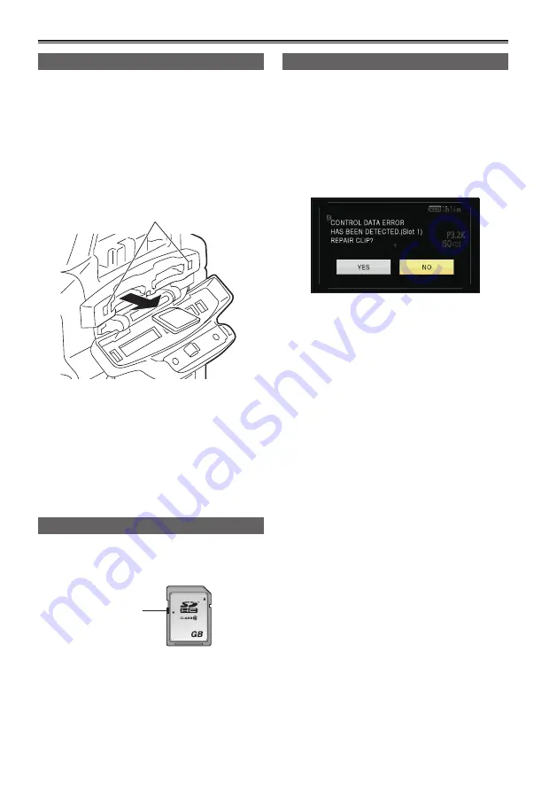
Repairing SD Memory Cards

Never remove the SD Memory Card or disconnect 

the battery or DC cord while the SD Memory Card 

access lamp is flashing, as doing so may damage 

the SD Memory Card. In the event that the SD 

Memory Card has been removed while the SD 

Memory Card access lamp was flashing, or that 

the battery or DC cord has been disconnected 

during recording or the recording finalization 

process, a repair verification screen will be 

displayed the next time the power is switched on in 

order to allow errors to be repaired.

Select YES to begin repairing. When repairing is 

complete, “REPAIR FINISHED” will be displayed, and 

the camera will switch to the recording paused screen.

Select NO to switch directly to the recording 

paused screen without repairing.

•  Memory cards cannot be repaired with the camera 

if NO is selected, but can still be repaired by using 

the AVCCAM Restorer

*

 contents repair software.

• An SD Memory Card on which an error occurred 

can be repaired by using either the camera 

that was used for the shooting, or the AVCCAM 

Restorer contents repair software.

• A repair confirmation message may be displayed 

after inserting an SD Memory Card which has no 

error, but repair will not be performed even when 

YES or NO is selected.

•  Repair may take up to 20 minutes or so depending 

on the places where the errors occurred on the card.

•  Use a battery with an adequate charge or the AC adaptor.

• If the repair operation has failed, “SYSTEM 

ERROR TURN POWER OFF” will be displayed. 

In this case, please use the AVCCAM Restorer 

contents repair software. 

Depending on the status of the data, it may not be 

possible to restore all data completely. In this case, 

it will no longer be possible to play back the clips 

that were recorded before the power was turned off.

•  Clips with a total recording time of less than 10 

seconds may not be able to be repaired.

•  Indexes attached during recording cannot be repaired.

*  

AVCCAM Restorer is included on the supplied 

CD-ROM. 

For details on how to install it, refer to install.txt.  

For details on how to use it, read the operating 

instructions (PDF file). 

The AVCCAM Viewer can also be downloaded 

from the following website. 

http://pro-av.panasonic.net/

Basic shooting operations (continued)

Summary of Contents for AVCCAM AG-AF100AP

Page 1: ...ENGLISH Vol 1 Volume 1 Note that Operation Instructions Vol 1 describes basic operations of the Memory Card Camera Recorder For instructions on advanced operations of the Memory Card Camera Recorder refer to Operating Instructions Vol 2 pdf file contained in the supplied CD ROM Register now http panasonic biz sav pass_e This product is eligible for the AVCCAM 3 Year Warranty Repair Program For det...

Page 2: ...hall be installed near the equipment and shall be easily accessible To completely disconnect this equipment from the AC mains disconnect the power cord plug from the AC receptacle CAUTION Danger of explosion or fire if battery is incorrectly replaced or mistreated Do not disassemble the battery or dispose of it in fire Do not store in temperatures over 60 C 140 F Do not expose the battery to exces...

Page 3: ...r installation If this equipment does cause harmful interference to radio or television reception which can be determined by turning the equipment off and on the user is encouraged to try to correct the interference by one of the following measures Reorient or relocate the receiving antenna Increase the separation between the equipment and receiver Connect the equipment into an outlet on a circuit...

Page 4: ... from being walked on or pinched particularly at plugs convenience receptacles and the point where they exit from the apparatus 11 Only use attachments accessories specified by the manufacturer 12 Use only with the cart stand tripod bracket or table specified by the manufacturer or sold with the apparatus When a cart is used use caution when moving the cart apparatus combination to avoid injury fr...

Page 5: ... enable verification as to whether they may be safely used with this product 1 Please note that this extended warranty is not available in some countries regions 2 Not all models eligible for extended warranty coverage 3 The basic warranty period may vary depending on the country region 4 Not all repair work is covered by this extended warranty Purchase AVCCAM product Register online within 1 mont...

Page 6: ...taching detaching the grip 26 The remote control 27 Insert the battery 27 Remote control usable range 27 Turn on off the camera 27 Tally lamp 28 Viewfinder 29 Using the viewfinder 29 Using the LCD 30 Emphasizing outlines 30 Adjusting the screen display 31 Changing backlight brightness 32 Setting the calendar 33 Shooting Basic shooting operations 35 Preparing for recording 35 Checking photos taken ...

Page 7: ...rnal units Nonlinear editing Displays Screen displays Menu Setup menu list Reference Before calling for service Updating the firmware incorporated into the unit Cleaning Storage Precautions How to handle data recorded on SD Memory Card How to open the operating instruction manual PDF files Discontinue installation if the installation screen of the software opens as a result of inserting the CD ROM...

Page 8: ...hirds Page 10 A separately available mount adaptor DMW MA1 is necessary SD SDHC SDXC Memory Card 32 LOCK Images can be recorded in HD high definition Please see page 73 of Vol 2 for details on the handling of recorded data A set number of user files can be recorded to and read from the SD Memory Card Page 21 of Vol 2 Computer Send data files to your computer for non linear editing etc 2 PC mode Pa...

Page 9: ... may result in damage to the lens mount Micro Four Thirds and Four Thirds are trademarks or registered trademarks of Olympus Imaging Corporation in Japan USA the EU and other countries Usable l Some functions features limited Not usable Lens Type AF 1 OnePush AF MF Camera Focus by Remote Control 60i 60P 30P 50i 50P 25P 24P Micro Four Thirds Lens H FS014045 Panasonic 2 l 3 l 4 H FS045200 Panasonic ...

Page 10: ... 24P mode 5 Limitations apply to the simultaneous operation of FOCUS and IRIS 6 A camera remote connected to CAM REMOTE jack S S terminal can control ZOOM Note use of H VS014140 lens for movie recording Micro Four Thirds mount is assumed throughout this operating instructions document For the latest information regarding supported lenses please refer to Panasonic catalogs web site etc http pro av ...

Page 11: ...rt from entering the camera To prevent damage to the lens connection be sure to attach the lens rear cap When using lenses other than those conforming to the Micro Four Thirds and Four Thirds Specifications set the LENS CHECK item on the OTHER FUNCTIONS screen of MENU settings to OFF Change lenses in a place that is relatively free of dust and dirt When the power switch is OFF or when carrying the...

Page 12: ... 6 GB 8 GB 12 GB 16 GB 32 GB SDXC Memory Card 48 GB 64 GB Please see our support page at the following website for the latest information not included in these operating instructions http pro av panasonic net This camera supports FAT12 FAT16 formatted SD memory cards FAT32 formatted SDHC memory cards and exFAT formatted SDXC memory cards that are compliant with the SD standard 4 GB or greater memo...

Page 13: ...nd SD Memory Cards as designated by the SD standards When the use of an SD speed class 6 card is recommended for SD compatible products this indicates that stable recording operation can be achieved when using SD Memory Cards of class 6 and above Cautions for usage Do not allow dirt water or other substances to come into contact with the connector part on the reverse of the card Do not leave the c...

Page 14: ...r battery charger Contact your dealer The battery takes longer to charge when it is warm The AC adaptor battery charger can interfere with radio reception so keep radios at least 1 meter away from it The AC adaptor battery charger may make some noise when you are using it but this is normal Take precautions not to drop the camera when moving it Strong impacts may damage the camera and cause it to ...

Page 15: ...nto the screen of the LCD or viewfinder if they are displayed for a long time but you can fix this by leaving the camera off for several hours The liquid crystal parts are highly precise with 99 99 of the pixels effective This leaves less than 0 01 of pixels that may not light or may remain on all the time These phenomena are normal and will have no effect on the images you shoot Condensation may ...

Page 16: ...the use of video and audio material you have recorded for any purpose other than your own personal enjoyment Remember that restrictions apply to the shooting of certain material even if it is intended for private use Caution regarding laser beams The MOS sensor may suffer damage if the lens is subjected to light from a laser beam Ensure that laser beams do not strike the lens when shooting in an e...

Page 17: ...arks of their respective companies This product is licensed under the AVC Patent Portfolio License for the personal and non commercial use of a consumer and no license is granted or shall be implied for any use other than the personal uses detailed below To encode video in compliance with the AVC standard AVC Video To decode AVC Video that was encoded by a consumer engaged in a personal and non co...

Page 18: ...y Cards SDHC SDXC Memory Cards cannot be used with non SDHC SDXC compatible equipment Ensure that all equipment is SDHC SDXC compatible when using card with other devices Compatibility of recorded video Recorded video cannot be used with non AVCHD compatible equipment For details please see your product s operating instructions Recorded video cannot be played back on non compatible non AVCHD compa...

Page 19: ...er Page 41 of Vol 2 Screws for cable clamper Length 4 mm M2 1 Page 41 of Vol 2 CD ROM Operating Instructions AVCCAM Restorer The following accessories are attached to the unit Bodycap Handle Grip INPUT 1 2 terminal cover 2 For part numbers for the battery see Optional accessories Please consult a retailer when purchasing additional accessories Adequately process the AC cord cap and the packaging m...

Page 20: ...f Vol 2 3 DISP MODE CHK button Page 6 of Vol 2 4 Viewfinder Page 29 5 Diopter adjustment dial Page 29 6 Built in speaker Page 40 of Vol 2 7 START STOP2 button Page 35 8 MENU button Page 44 9 EXEC button Page 35 of Vol 2 10 OPERATION lever 11 AUDIO MON ADV button Pages 12 and 40 of Vol 2 12 LCD monitor Page 30 Page 45 of Vol 2 13 Built in microphone Page 17 of Vol 2 14 Light shoe 15 Major hook 16 N...

Page 21: ... Page 27 15 Tally lamp rear Page 28 16 Battery compartment Page 25 17 Battery release button Page 25 18 Card slot cover and OPEN lever Page 38 19 AUDIO OUT CH1 CH2 terminal Page 42 of Vol 2 20 VIDEO OUT terminal Page 42 of Vol 2 21 USB terminal Page 42 of Vol 2 22 HDMI OUT terminal Page 42 of Vol 2 23 INDEX REMOTE jack 2 5mm stereo mini jack 24 CAM REMOTE jack FOCUS IRIS 3 5mm mini jack S S 2 5mm ...

Page 22: ...utton Page 11 of Vol 2 2 ZEBRA button Page 5 of Vol 2 3 OIS button Page 11 of Vol 2 4 EVF DTL button Page 30 5 WFM button Page 12 of Vol 2 6 COUNTER RESET TC SET button Page 24 of Vol 2 7 CH1 CH2 SELECT switch Page 17 of Vol 2 8 INPUT 1 2 switch MIC POWER 48V Page 17 of Vol 2 9 Tripod hole bottom side Page 16 10 Lens detachment button Page 11 11 AWB button Page 41 12 White balance sensor Page 43 1...

Page 23: ... 2 11 OPERATION buttons Same function as the Operation lever on the camera 12 MENU button Same function as the MENU button on the camera 13 PHOTO SHOT button Page 13 of Vol 2 Same function as the CAPTURE feature assigned to a USER SW function on the camera ZOOM START STOP PHOTO SHOT EXT DISPLAY DATE TIME VOL PLAY STOP SKIP SKIP MENU ENTER PAUSE SEARCH STILL ADV STILL ADV SEARCH 3 4 6 8 1 2 5 7 8 9...

Page 24: ...ter a brief pause Description of parts continued The battery display will change as battery capacity decreases will be displayed in red when less than 3 minutes are remaining and will flash when the battery is empty Remaining battery capacity may not be displayed correctly when using in high or low temperatures or when the battery has not been used for a long period of time To ensure that remainin...

Page 25: ...ace DC cord s battery connector Removal 1 Set the POWER switch to OFF and check that the mode lamp is off 2 Remove the DC cord s battery connector while pressing the battery release button 3 Disconnect the AC power supply cord from the power outlet Battery cannot be recharged when the DC cord is connected to the AC adaptor Disconnect the AC power supply cord from the power outlet when the unit is ...

Page 26: ...detach Attaching the handle Carry out the reverse of the detaching procedure to attach the handle Ensure both screws are firmly fixed in place When holding the handle make sure the screws are not loose Screws Attaching detaching the grip Detaching the grip 1 Use a Philips head screwdriver and remove the two screws 2 Slide in the direction of the arrow The grip will detach Attaching the grip Carry ...

Page 27: ...er strong light the unit may not operate properly even within the usable ranges The remote control is set to OFF in the factory settings When using the remote control set the IR REMOTE item in the OTHER FUNCTIONS screen to ON Page 62 of Vol 2 Turn on off the camera Set the POWER switch to ON Turn on the camera The mode lamp CAM lights red CAMERA mode and the camera is now in the recording pause mo...

Page 28: ...ote control operation flashes 8 times per second Recording error has occurred flashes 4 times per second Battery is low flashes 4 times per second Available SD Memory Card capacity is low flashes 4 times per second Remaining battery capacity is low flashes once per second Remaining memory of the SD Memory Card is low flashes once per second Lamps specified via the TALLY LAMP setting flashes upon r...

Page 29: ...llow the eyepiece of the viewfinder to remain in direct contact with sunlight or other strong light sources Internal components may be damaged and fire may be caused if light accumulates through the lens When the LCD monitor is open the viewfinder may not display anything Close the LCD monitor Page 43 of Vol 2 Viewfinder Fitting the eye cup Attach the eye cup by aligning the projections on the eye...

Page 30: ...s of the images you see in the viewfinder or on the LCD makes it easier to focus Emphasizing the outlines does not effect the images you shoot 1 In CAM mode press EVF DTL button EVF DTL ON appears on the screen for about 2 seconds MENU START STOP 2 PUSH ENTER MODE POWER DISP MODECHK USER 1 USER 2 FUNCTION FOCUS IRIS GAIN WHITEBAL B MEGA ON OFF O I S CAM ON CH1 CH2 AUDIO LEVEL OFF PB AUDIO MON BARS...

Page 31: ...he setting menu DISPLAY SETUP screen LCD monitor adjustments Set YES under LCD SET on the setting menu DISPLAY SETUP screen 4 Select the desired item by tilting the Operation lever in the directions and push the Operation lever 5 Adjust the selected item by tilting the Operation lever in the directions 6 Press MENU button to exit the menus The viewfinder display can be in color or black and white ...

Page 32: ...backlight can be adjusted between five different settings 1 Select LCD BACKLIGHT from the setup menu DISPLAY SETUP screen 2 Select and set a value in the range of 1 to 3 The greater the value the brighter the screen This setting will remain saved even if the camera s power is switched off ...

Page 33: ... the Operation lever or tilt lever in direction 4 Pushing the Operation lever twice brings up the setting screen Tilt the Operation lever in the directions to set the time difference from Greenwich Mean Time and push the Operation lever again Factory default setting is 00 00 Setting the calendar 5 Tilt the Operation lever in the direction and select YES in the CLOCK SET item on the settings menu O...

Page 34: ...ation lever again The clock can vary in accuracy so check that the time is correct before shooting When using the camera overseas do not set the CLOCK SET option to the local time but instead enter the time difference from Greenwich mean time according to TIME ZONE Page 63 of Vol 2 Setting the calendar continued ...

Page 35: ...the camera and backup images have been recorded The REC CHECK function does not work when PC has been selected as the operation mode This function does not work if the REC format is changed if the camera is set to the CAM mode after having been switched to the PB mode if the SD memory card slot cover is opened or if the slot is switched after shooting Preparing for recording 1 Turn the POWER switc...

Page 36: ... access lamp of the slot for recording lights up orange This function works when a recordable SD card is inserted in both slots The slot cannot be switched during recording Formatting SD Memory Cards 1 Set the camera s power switch to ON Page 27 2 Press the MENU button 3 Select CARD FUNCTIONS CARD FORMAT from the menu and then push the OPERATION lever to confirm Select the slot number of the card ...

Page 37: ...ss 2 or above when recording in HE mode 3 PH mode This is the highest quality mode in 1080i 720P format PS mode This is the highest quality mode in 1080P format 4 Use a memory card of SD speed class 6 or above when recording with PS mode Recording cannot be performed with a memory card of lower than SD speed class 6 This camera uses the VBR recording system VBR stands for Variable Bit Rate and it ...

Page 38: ... repairing is complete REPAIR FINISHED will be displayed and the camera will switch to the recording paused screen Select NO to switch directly to the recording paused screen without repairing Memory cards cannot be repaired with the camera if NO is selected but can still be repaired by using the AVCCAM Restorer contents repair software An SD Memory Card on which an error occurred can be repaired ...

Page 39: ...witches to manual focus The FOCUS switch automatically moves back to M MANUAL after you move it to Temporarily switching to auto focus Even if you have switched FOCUS to M MANUAL the camera will focus automatically while you press down PUSH AUTO Auto focus may not work properly if there is flickering Select a shutter speed suited to the ambient light Page 14 of Vol 2 If the auto focus mode is set ...

Page 40: ...the red outline Adjust the focus so that the subject to focus is surrounded by the red outline EXPAND 1 Assign EXPAND to any of the USER 1 3 button in the menu SW MODE screen 2 Press the button assigned USER SW The center of the screen displayed on the LCD monitor is enlarged The screen border of the LCD monitor turns blue in enlarged view Only four items are displayed on the screen the counter au...

Page 41: ...used filter to change light intensity 1 ND filter is not used 2 Cuts light intensity by up to about 1 4 3 Cuts light intensity by up to about 1 16 4 Cuts light intensity by up to about 1 64 MENU START STOP 2 PUSH ENTER MODE POWER DISP MODECHK USER 1 USER 2 FUNCTION FOCUS IRIS GAIN WHITEBAL B PUSHAUTO MEGA ON OFF O I S CAM ON CH1 CH2 AUDIO LEVEL OFF PB AUDIO MON EXEC A PRST L M H A M ND dial Adjust...

Page 42: ...e balance again Error messages Adjustments LOW LIGHT Increase light or increase the gain LEVEL OVER Reduce light or decrease the gain If the messages repeatedly appear even after trying a number of times consult your dealer Basic operations of the camera continued Using presets Use this feature when you have no time to make white balance adjustments 1 Set the WHITE BAL switch to PRST The current w...

Page 43: ...re proceeding Message during adjustment ABB ACTIVE Message after adjustment ABB END Black balance can be adjusted by holding the AWB button down even when the ATW function is in use You cannot adjust the black balance while you are shooting Black balance adjustment takes around 30 seconds when the shutter speed is 1 8 or less If ABB NG message appears attach the lens cover then try adjusting the A...

Page 44: ...onitor CAM mode Example PB mode Example 2 Tilt the Operation lever in the directions to move the yellow cursor to the function you wish to set 3 Push the Operation lever or tilt in the direction to display the setting items Example 4 Tilt the Operation lever in the directions to move the yellow cursor to the item you wish to set Example 5 Push the Operation lever or tilt in the direction to set th...

Page 45: ...rately To initialize the user file i e all the settings other than the scene file settings Select INIT in LOAD SAVE INIT of the USER FILE screen The current menu settings of user file will return to the factory settings To initialize the scene file Of the six scene files select the file you want to initialize from the SCENE SELECT item in the SCENE FILE screen Then in the SCENE FILE screen LOAD SA...

Page 46: ...R3 SW COLOR TEMP Ach WFM COLOR TEMP Bch S S SW INH MASTER PED FACE FRAMING A IRIS LEVEL DRS RECORDING SETUP PREREC MODE GAMMA Page 56 of Vol 2 INTERVAL REC KNEE RELAY REC MATRIX PS PH AUDIO MODE SKIN TONE DTL MIC ALC B W MODE MIC GAIN1 CARD READ MIC GAIN2 CARD WRITE LOAD SAVE INIT NAME EDIT TC MODE TCG TC UB SETUP TD PRESET Page 57 of Vol 2 UB PRESET EXT TC LINK AV IN OUT SETUP SDI OUT Page 58 of ...

Page 47: ...RY USER CLIP NAME OTHER DISPLAY META DATA PROP LCD BACKLIGHT CLIP COUNTER RST LCD SET META INIT SET EVF SET SELF SHOOT EVF MODE EVF COLOR LENS CHECK IR REMOTE TALLY LAMP CLOCK SET OTHER FUNCTIONS TIME ZONE Pages 62 to 64 of Vol 2 POWER SAVE LANGUAGE ACTIVATE EXPORT PRODUCT SERIAL SYSTEM FREQ Page 64 of Vol 2 IMPORT ACTIVATION CODE SYSTEM INFO ACTIVATION LIST LENS INFO MENU INIT PLAY SETUP PB FORMA...

Page 48: ...set when SYSTEM FREQ is 59 94 Hz 60i 60P mode 1 60 1 100 1 120 1 250 1 500 1 1000 1 2000 seconds 30P mode 1 30 1 50 1 60 1 120 1 250 1 500 1 1000 1 2000 seconds 24P mode 1 24 1 50 1 60 1 120 1 250 1 500 1 1000 1 2000 seconds when SYSTEM FREQ is 50 Hz 50i 50P mode 1 50 1 60 1 120 1 250 1 500 1 1000 1 2000 seconds 25P mode 1 25 1 50 1 60 1 120 1 250 1 500 1 1000 1 2000 seconds Underline indicates wh...

Page 49: ...R Interval recording Start 1 second 10 seconds 30 seconds 1min 2min Recording mode is fixed to PH 1080 24P when SYSTEM FREQ is 59 94 Hz PH 1080 25P when SYSTEM FREQ is 50 Hz and the maximum shooting time is 24 hours VFR recording When REC FORMAT is 1080 24P 30P 12 15 18 20 21 22 24 25 26 27 28 30 32 34 36 40 44 48 54 60 frame sec When REC FORMAT is 1080 25P 12 15 18 20 21 22 23 24 25 26 27 28 30 3...

Page 50: ... 5mm diameter TC PRESET IN OUT terminal VIDEO terminal dual purpose IN 1 0 V 4 0 V p p 10 kΩ OUT 2 0 V 0 5 V p p Low impedance USB terminal Card reader writer function no copyright protection support Type mini B connector compliant with USB ver 2 0 Monitor LCD 3 45 type wide LCD color monitor 920 000 dots approx Viewfinder wide 0 45 type LCD color monitor 1 220 000 dots equivalent approx Specifica...

Page 51: ...Memo 51 ...

Page 52: ...he European Union These symbols are only valid in the European Union If you wish to discard this product please contact your local authorities or dealer and ask for the correct method of disposal EU Web Site http panasonic net Panasonic Corporation 2012 ...

Reviews: