


Turquoise Stroke Switches (ASQ1)
Panasonic Corporation Electromechanical Control Business Division
industrial.panasonic.com/ac/e/
AECTB6E 202110
Panasonic Corporation 2021
RATING
Contact rating
1 mA 5 V DC to 100 mA 30 V DC
Note: Please consult us regarding 42 V DC rating.
Operation environment and conditions
Item
Specifications
Ambient and storage temperature
–40 to +85°C (no freezing and condensing)
Allowable operating speed
30 to 500 mm/sec
Max. operating cycle rate
120 cpm
Note: When switching at low and high speeds or under vibration, or in high-temperature, high-humidity environments, life and performance may be reduced significantly depending
on the load capacity. Please consult us.
Electrical characteristics
Dielectric strength (Initial)
Between non-continuous terminals: 600 Vrms.
Between each terminal and other exposed metal parts: 1,500 Vrms.
Between each terminal and ground: 1,500 Vrms. (at detection current of 1 mA)
Insulation resistance (Initial)
Min. 100
MΩ (at
500 V DC insulation resistance meter) (Locations measured same as dielectric strength.)
Contact resistance (Initial)
Max. 1
Ω (by voltage drop
0.1 A 6 to 8 V DC)
Characteristics
Item
Specifications
Electrical
switching
life
5 V DC 1 mA (Resistive load)
Min. 5 × 10
5
Note 1)
Switching frequency: 20 times/min
Conduction ratio: 1:1
Pushbutton operation speed: 100 mm/s
Pushbutton switching position: free position (FP) to operation limit position (TTP)
16 V DC 50 mA (Resistive load)
Min. 5 × 10
5
Note 2)
30 V DC 100 mA (Resistive load)
Min. 2 × 10
5
Note 2)
Vibration resistance
(malfunction vibration resistance)
Single amplitude: 0.75 mm
Amplitude of vibration: 10 to 55 Hz (4 minutes cycle)
Direction and time: 30 minutes each in X, Y and Z directions
Amplitude of vibration: 5 to 200 Hz (10 minutes cycle)
Acceleration: 43.1 m/s
2
Direction and time: 30 minutes each in X, Y and Z directions
Shock resistance
(malfunction shock resistance)
Shock value: 980 m/s
2
Direction and time: 5 times each in X, Y and Z directions
Vibration resistance endurance
Frequency of vibration: 33.3 Hz,
Acceleration: 43.1 m/s
2
Direction and time: 8 hours each in X, Y and Z directions
Terminal strength
6 N min (each direction) *Terminal deformation possible.
Heat resistance
85°C 500 hours
Cold resistance
–40°C 500 hours
Humidity resistance
40°C 95% RH 500 hours
Thermal shock resistance
30 min at 85°C to 30 min at –40°C for 1,000 cycles
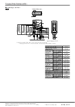
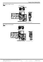
Unit weight
Approx. 0.8 g (terminal type), Approx. 5.4 g (wire leads side type)
Protection grade
IP67 (except exposed terminal part of terminal type)
Note: As long as there are no particular designations, the following conditions apply to the test environment.
• Ambient temperature: 5 to 35°C
• Relative humidity: 25 to 85% RH
• Air pressure: 86 to 106 kPa
Note 1: Switching life for single switching (COM-NC or COM-NO connection) and double switching (COM-NC and COM-NO connection).
Note 2: Switching life is for single switching life. For double switching it is min. 10
5
times.
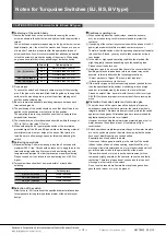
Protection grade
1) JIS C0920 (water-resistance experiments for electrical
machines and protection rating against incursion of solid
substances): Immersion protected
(Note 1)
2) IEC 60529 (rating for outer shell protection): IP67
(Immersion protected)
(Note 1)
3) JIS D0203 (method for testing moisture resistance and
water resistance in automotive components): D2
(Note 2)
Note 1) A concrete testing method is to check for any adverse effect on the structure
after leaving it submerged for 30 minutes under 1 m of water (with temperature
difference between water and switch no larger than 5°C).
Note 2) A concrete testing method is to check for any adverse effect on the structure
after leaving it submerged for 10 minutes under 10 cm water (with temperature
difference between water and switch no larger than 30°C).
ー 3 ー


