AJ8 (J8)
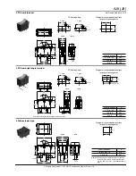
3. PC board terminal
ON
OFF
30
15
2-pole
1-pole
12.8
10
19.5
16
7.7
(7.5)
12.5
4.375
8.75
0.8
28
15
2
2
4
32
°
±
4
PC board pattern
15
±
0.1
8.75
±
0.1
3
±
0.2
1.2
±
0.1
15
±
0.1
3
±
0.2
1.2
±
0.1
4.375
±
0.1
2-pole
1-pole
Diagram of recommended locations
for panel mounting holes
12.9
+
0.1
−
0
X
Panel thickness
X
0.75 to 1.25
28.2
1.25 to 2
28.4
2 to 3
28.8
+
0
−
0.1
+
0
−
0.1
+
0
−
0.1
mm General tolerance:
±
0.5
4. PC board right angle terminal
Remark: Left angle terminal type is also available.
OFF
ON
15
2-pole
1-pole
12.8
10
12.5
4
8 0.8
2
30
19.5
16
7.7
28
2
32
°
±
4
PC board pattern
15
±
0.1
8
±
0.1
3
±
0.2
15
±
0.1
3
±
0.2
1.2
±
0.1
1.2
±
0.1
4.375
±
0.1
2-pole
1-pole
Diagram of recommended locations
for panel mounting holes
Terminal side
12.9
+
0.1
−
0
X
21.0
±
0.3
17.5
±
0.3
Panel thickness
X
0.75 to 1.25
28.2
1.25 to 2
28.4
2 to 3
28.8
+
0
−
0.1
+
0
−
0.1
+
0
−
0.1
5. Wide actuator type
OFF
ON
32
32
°
±
4
25
2-pole
1-pole
21.8
19
19.5
16
7.7
10.6
21
4.375
8.75
29.4
15
6.35
4.4
1.75 dia.
0.8
2
Diagram of recommended locations
for panel mounting holes
Remark: Dimensions for the terminals of soldering
terminal type and PC board terminal type
are the same as those of standard actuator
type.
Panel thickness
X
1 to less than 1.8
30.0
1.8 to 2.3
30.7
22.0
+
0.1
−
0
X
+
0
−
0.1
+
0
−
0.1
All Rights Reserved © C
OPYRIGHT
Matsushita Electric Works, Ltd.


