background image

9

Parts and their functions (continued)

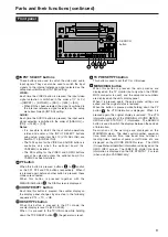
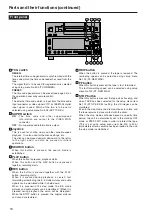
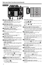
INPUT SELECT buttons

These buttons are used to switch the video and audio
input signals. They can also be used to switch the input
signals to the internal reference signal selected as the
setup menu item No.600 (INT SG) setting.

VIDEO: 

Each time the VIDEO button is pressed, the input video
signal selection is switched in the order of [Y P

B

P

R

]

[CMPST] 

[S-VIDEO] 

[SDI] 

[1394] 

[SG].

When SG has been selected, the signal is switched to
the internal reference signal selected as the setup
menu item No.600 (INT SG) setting.

AUDIO: 

Each time the AUDIO button is pressed, the input audio
signal selection is switched in the order of [ANALOG] 

[SDI] 

[1394] 

[SG].

Notes:

It is possible to inhibit the input switch operations
(video and audio) of the INPUT SELECT buttons
using setup menu item No.112 (V IN SEL INH) and
item No.113 (A IN SEL INH).

The 1394 option for the VIDEO and AUDIO buttons is
available only when the optional board (AJ-
YAD255G) is installed.

The SDI setting for the VIDEO and AUDIO buttons
cannot be selected unless the optional board (AJ-
YA94G) has been installed.

PF button

When this button is pressed, buttons 

to 

function

as the PF1, PF2 and PF3 buttons, respectively.  When it
is pressed again before another button is pressed, these
modes are canceled.
When this button is pressed together with the

MENU/DIAG button 

, the DIAG screen is displayed.

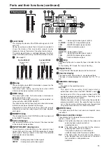
COUNTER/PF1 button

Each time this button is pressed, the counter display on
the display panel changes by one step in the following
sequence: CTL 

TC 

UB.

RESET/PF2 button

When this button is pressed in the CTL mode, the
counter display is reset to [00:00:00:00].
When it is pressed in the TC/UB mode while holding

down the TC PRESET button 

, the generator is reset.

TC PRESET/PF3 button

This button is used to set the TC or UB values.

MENU/DIAG button

When this button is pressed, the setup menus are
displayed on the TV monitor (but only when the VIDEO
MON connector is used), and the setup menu numbers
are displayed on the unit’s display panel.
When it is pressed again, the setup menu settings are
exited, and the original status is restored.
When the button is pressed while holding down the PF

button 

, the VTR information is displayed.  When it is

pressed again, the original display is restored.  The VTR
information consists of the WARNING, HOURS METER,
UMID and DIF STATUS 1, 2 information.  The SEARCH
button is used to switch the displays between these kinds
of information.
Descriptions of the warnings are displayed on the
WARNING screen.  The deck’s serial number, power-on
time, drum rotation time, tape travel time, number of
loading times, number of power on/off times, etc. are
displayed on the HOURS METER screen.  The UMID
(Unique Material Identifier) information is displayed on the
UMID INFO screen. The IEEE1394 digital interface
information is displayed on the DIF STATUS 1, 2 screen
(when using AJ-YAD255G only). 

S E A R C H
button

CH 1

CH 2

CH 3

CH 4

REC

PB

Digital Video Cassette Recorder AJ-

SUPER

ON

OFF

TCG

REGEN

PRESET

EXT

INT

COUNTER

PF

PF1

PF2

PF3

DIAG

MENU

PUSH

SHTL/SLOW

TC 

PRESET

METER

FULL/FINE

MONITOR SEL

RESET

UNITY VAR

INPUT SELECT

VIDEO

AUDIO

HEADPHONES

SEARCH

EJECT

POWER

REC INHIBIT

CONTROL

ON

ON

OFF

OFF

LOCAL

REMOTE

REC

PLAY

FF

REW

STOP

CH 1

CH 2

CH 1

CH 2

REC

PB

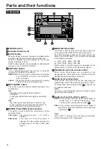
Front panel

Summary of Contents for AJ-SD255 - Professional Editing Video Cassete...

Page 1: ...eo Cassette Recorder Operating Instructions AJ P AJ E Model No ENGLISH VQT0L63 S1204N0 M Printed in Japan D Before operating this product please read the instructions carefully and save this manual for future use ...

Page 2: ...NLY CAUTION TO REDUCE THE RISK OF FIRE OR SHOCK HAZARD REFER MOUNTING OF OPTIONAL INTERFACE BOARDS TO QUALIFIED SERVICE PERSONNEL CAUTION TO REDUCE THE RISK OF FIRE OR SHOCK HAZARD REFER CHANGES OF SWITCH SETTINGS INSIDE THE UNIT TO QUALIFIED SERVICE PERSONNEL CAUTION This apparatus can be operated at a voltage in the range of 100 240 V AC Voltages other than 120 V are not intended for U S A and C...

Page 3: ...laced If you lose the fuse cover the plug must not be used until a replacement cover is obtained A replacement fuse cover can be purchased from your local Panasonic Dealer FOR YOUR SAFETY PLEASE READ THE FOLLOWING TEXT CAREFULLY This product is equipped with 2 types of AC mains cable One is for continental Europe etc and the other one is only for U K Appropriate mains cable must be used in each lo...

Page 4: ...IRE OR SHOCK HAZARD DO NOT EXPOSE THIS EQUIPMENT TO RAIN OR MOISTURE TO REDUCE THE RISK OF FIRE OR SHOCK HAZARD KEEP THIS EQUIPMENT AWAY FROM ALL LIQUIDS USE AND STORE ONLY IN LOCATIONS WHICH ARE NOT EXPOSED TO THE RISK OF DRIPPING OR SPLASHING LIQUIDS AND DO NOT PLACE ANY LIQUID CONTAINERS ON TOP OF THE EQUIPMENT CAUTION TO REDUCE THE RISK OF FIRE OR SHOCK HAZARD REFER MOUNTING OF OPTIONAL INTERF...

Page 5: ...erface 14 Joystick 15 PF Programmable Function 15 Repeat playback 16 Setup initial settings 17 Setup menus 18 SYSTEM menu 20 USER menu 21 BASIC 21 OPERATION 23 INTERFACE 24 TAPE PROTECT 25 TIME CODE 26 VIDEO 28 AUDIO 30 V BLANK 32 DIF 33 MENU 34 Time code user bit 35 Superimpose screen 36 Condensation 37 Maintenance 37 Audio input impedance 37 Error messages 38 Specifications 43 ...

Page 6: ...s This high picture quality VTR incorporates digital compression technology to reduce the deterioration of the picture quality and sound quality resulting from dubbing It has a compact and lightweight design so that it can readily be carried around or easily installed in a rack 3 pin power cord x 1 Included accessories IEEE1394 interface board AJ YAD255G SDI interface board AJ YA94G Use only the o...

Page 7: ...ion buttons The unit comes with three PF buttons Any three frequently used setup menus can be selected and by operating these buttons on the front panel it is possible to change the menu settings Recording and playback of UMID information Recording and playback of UMID Unique Material Identifier information complies with the SMPTE 330M standard UMID information can be checked on the DIAG menu UMID...

Page 8: ...g METER FULL FINE selector button This button is used to select the scale display for the audio level meter FULL mode The standard scale to 0 dB is selected FINE mode The scale in 0 5 dB increments is selected The position indicates the standard level of 20 dB 18 dB See page 11 MONITOR SEL button This button is used to select the audio signals which are to be output to the AUDIO MON L and R connec...

Page 9: ...2 button When this button is pressed in the CTL mode the counter display is reset to 00 00 00 00 When it is pressed in the TC UB mode while holding down the TC PRESET button the generator is reset TC PRESET PF3 button This button is used to set the TC or UB values MENU DIAG button When this button is pressed the setup menus are displayed on the TV monitor but only when the VIDEO MON connector is u...

Page 10: ...button is pressed the search mode is established PLAY button When this button is pressed playback starts When this button and the REC button are pressed together recording starts REC button When this button is pressed together with the PLAY button recording starts When it is pressed during playback a search fast forwarding or rewinding the E E mode pictures and audio signals can be monitored while...

Page 11: ...ted signals 1394 IEEE1394 digital signals option SG Internal reference signal ANALOG Analog audio signals SDI Serial digital audio signals option 1394 IEEE1394 digital signals option SG Internal reference signal lamp This lamp lights when a cassette tape is inserted into the VTR In the standby OFF mode this lamp is flashing Repeat lamp This lights when the repeat play mode has been set Counter dis...

Page 12: ...tor Note The wide ID superimposed on the input signals is not detected ANALOG VIDEO OUT connectors The signals which are to be output from these connectors are selected as follows by setting the ANALOG VIDEO OUT selector switch Y PB PR bottom position Analog component video signals are output VIDEO1 VIDEO2 top position Two sets of analog composite video signals are output from connectors and Y C m...

Page 13: ...ssette tapes From the perspective of protecting consumer use DV and DVCAM cassette tapes minimize the number of times the tapes are cued up at the same locations as much as possible When consumer use DV and DVCAM cassette tapes are used the maximum time for STILL TIMER is set to 20 seconds The audio sampling rate recorded to consumer DV tapes is 48 kHz When using the IEEE1394 interface board optio...

Page 14: ...re monitored using another device they may differ from the video and audio signals played back by this unit Recording tape DVCPRO DV Input data DVCPRO DV DVCPRO DV Recording format DVCPRO DVCPRO 1 DV DV Recording tape DVCPRO DV Input data DVCPRO DV DVCPRO DV Recording format DVCPRO Cannot record or receive data Cannot record or receive data DV The recording format for IEEE1394 digital input data i...

Page 15: ...ation screen appears Press the PLAY button to set Registering the items in the PF buttons 1 When the PF button is pressed the registered items are displayed on the monitor screen which is output from the VIDEO MON connector 2 Press the PF1 PF2 or PF3 button that corresponds to the item whose setting is to be changed Each time the button is pressed the setting is updated in sequence 3 When the PF b...

Page 16: ...epeat playback mode 3 Press the MENU button A confirmation screen now appears The settings are stored in the memory if the PLAY button is now pressed Notes The picture quality deteriorates when repeat playback is initiated for the same tape over and over again As a general rule of thumb replace the tape with a new one after playing back the tape for about 100 times The output images to be displaye...

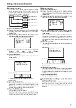
Page 17: ... cursor on the menu screen moves and the item number on the display flashes When the FF or REW button is pressed while holding down the PLAY button what is on the display is replaced with the next or previous major item 3 Incline the joystick to the left or right at the position where the change is to be made The setting is now changed To return what has been established as the setting to the fact...

Page 18: ...CH button and use the joystick to select whether the lock mode is to be set or released To set the lock mode Select 0001 ON as the setting To release the lock mode Select 0000 OFF as the setting When the lock mode has been set LOCKED flashes on the menu screen The counter display stops flashing and remains lighted 5 Press the MENU button A confirmation screen now appears 6 When the PLAY button is ...

Page 19: ...he USER1 menu display appears 7 Press the MENU button A confirmation screen now appears When the PLAY button is pressed the USER1 settings are stored in the memory If the settings are not to be stored in the memory press the STOP button instead Saving user files 1 Press the MENU button 2 Press the REW button or FF button while holding down the PF button to select the USER1 file 3 Operate the joyst...

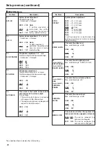
Page 20: ... 0002 1 4 52 µsec 0003 0 0 sec 0004 1 4 52 µsec 0005 2 8 96 µsec 0006 3 13 4 µsec Note If setting operation is performed the setting value does not return to factory default setting 22 VIDEO LEVEL This sets the video level Max variable range 3 dB 0000 128 0128 0 0255 127 24 For AJ SD255P HUE For AJ SD255E CHROMA PHASE This sets the hue chroma phase Max variable range 30 0000 128 0128 0 0255 127 25...

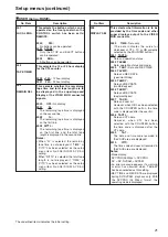
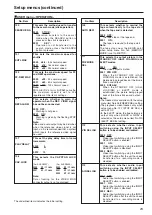
Page 21: ... TIME and REC DATE are displayed during DV DVCAM playback only With the DVCPRO 25 Mbps format the operating mode is displayed No Item Description 001 LOCAL ENA This selects the buttons which can be operated on the front panel when the CONTROL switch has been set to REMOTE 0000 DIS No buttons can be operated 0001 ST EJ Only the STOP and EJECT buttons can be operated 0002 ENA All buttons can be oper...

Page 22: ...r right When the DISPLAY SEL status causes characters to extend beyond the edges of the screen the setting value is changed but the characters are automatically displayed at a position on the screen where they will not extend For AJ SD255E 0000 0 0023 23 0028 28 For AJ SD255P 0000 0 0018 18 0022 22 011 CHARA TYPE This selects the display type for the super display output to the VIDEO MON connector...

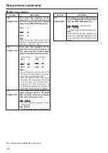
Page 23: ...ure in the STANDBY OFF HALF LOADING and EJECT modes 0000 DIS The video output is muted 0001 STB OFF When the STANDBY OFF HALF LOADING mode is established the picture being played back at the time is frozen and output 0002 SOF EJ When the STANDBY OFF HALF LOADING or EJECT mode is established the picture being played back at the time is frozen and output Notes The freeze status complies with the set...

Page 24: ...reached 161 CTL BGN or TC BGN This sets the BEGIN point in the repeat play mode Whether TC or CTL is displayed on the counter when the COUNTER button is pressed is set here When there is no setting appears and the tape start serves as the BEGIN point 162 END This sets the END point in the repeat play mode Whether TC or CTL is displayed on the counter when the COUNTER button is pressed is set here ...

Page 25: ...ING mode when the total time during which it has been left standing in the STOP mode reaches 30 minutes or 1 minute for a DV DVCAM tape 404 DV STILL TMR This menu item is for selecting the time to elapse before the tape protection mode is established when a DV or DVCAM tape is being used It is for selecting the time to elapse before the tape protection mode is established when the VTR has been lef...

Page 26: ...selected by setup menu items No 501 VITC POS 1 and No 502 VITC POS 2 0000 BLANK VITC signals are not output 0001 THRU VITC signals are output 501 VITC POS 1 This sets the position where the VITC signal is to be inserted Notes The same line as the one used for the setup menu items No 502 VITC POS 2 and No 662 UMID POS setting cannot be set The default settings are not restored even if the RESET but...

Page 27: ...de generator value in the VAUX area 0000 OFF The internal time code generator value is not recorded in the VAUX area When video signals on which the time code has been recorded are input the time code of the input signals is recorded in the VAUX area 0001 ON The internal time code generator value is recorded in the VAUX area 513 RUN MODE This sets the operation mode which is to make the internal t...

Page 28: ...14 PB PR OUT LV For AJ SD255P This selects the analog component output level 0000 M M level 0001 B CAM ß CAM level No Item Description 622 SETUP For AJ SD255P For setting 7 5 setup processing to be performed on input and output signals When the STOP button is pressed operation is transferred to the sub screen and the setup level is set for each output To return from the sub screen press the STOP b...

Page 29: ...her than 1394 signals the wide signals will not be detected Select WIDE as the setting when recording the wide screen information on the tape Regardless of the above setting the wide screen information cannot be superimposed onto tape playback and output No Item Description USER menu VIDEO No Item Description 662 UMID POS This sets the line on which the UMID information is to be superimposed Notes...

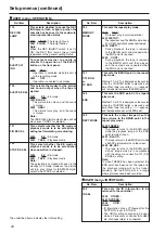
Page 30: ...ced CUT 0002 FADE Forced FADE 728 EMBEDDED AUD This selects whether to superimpose the audio data onto the SDI output 0000 OFF Data is not superimposed 0001 ON Data is superimposed YA94G Setup menus continued The underlined items indicates the initial setting No Item Description USER menu AUDIO 701 CH1 IN LV This selects the audio input CH1 reference level switching 0000 4dB 0001 0dB 0002 20dB 702...

Page 31: ...he sound is not muted 0001 ON The sound is muted 752 DV OUTPUT This selects the AUDIO CH1 and CH2 output signals during DV or DVCAM format playback 0000 ST1 The CH1 track signals are output to CH1 and the CH2 track signals to CH2 Only the sound during shooting is output 0001 ST2 The CH3 track signals are output to CH1 and the CH4 track signals to CH2 Only the audio dubbing sound is output 0002 ST1...

Page 32: ...EC LINE1 13 REC LINE14 For selecting the lines in which the teletext signals are to be recorded For AJ SD255E 0000 OFF 0001 7 320 0002 8 321 0003 9 322 0004 10 323 0005 11 324 0006 12 325 0007 13 326 0008 14 327 0009 15 328 0010 16 329 0011 17 330 0012 18 331 0013 19 332 0014 20 333 0015 21 334 0016 22 For AJ SD255P 0000 OFF 0002 11 274 0003 12 275 0004 13 276 0005 14 277 0006 15 278 0007 16 279 0...

Page 33: ...DIF AUD IN For AJ SD255P This selects the channels to be used for recording on the tape when DV format data with audio signals in the 4CH mode are to be input and then recorded on a DVCPRO tape 0000 CH1 2 Received DV format data CH1 and CH2 are selected 0001 CH3 4 Received DV format data CH3 and CH4 are selected 891 DIF DV AUDIO This sets the forced audio mode conversion when a DV tape is played a...

Page 34: ...n A02 P ON LOAD This loads the contents of the selected user file into USER1 and it starts operation with the USER1 settings when the power is turned on 0000 OFF Operation is started with the settings of the previously set user file 0001 USER2 The contents of USER2 are loaded into USER1 and operation is started with the USER1 settings 0002 USER3 The contents of USER3 are loaded into USER1 and oper...

Page 35: ...T In this mode recording is commenced from the value which was set by the TC PRESET button 5 To preset the time code or user bit take the following steps Set the TCG switch to PRESET Select TC or UB using the COUNTER button When the TC PRESET button is pressed operation is transferred to the setting mode and the setting digits start flashing on the counter display Operate the joystick and set the ...

Page 36: ...etup menu No 505 EXT TC SEL Setup menu No 514 VITC GEN Selected video input signal OFF Internal TCG value Timecode on IEEE1394 digital input VAUX area VITC on input video signal 3 Timecode from TIME CODE IN connector input 1 Timecode on IEEE1394 digital input VAUX area VITC on input video signal 3 Timecode on IEEE1394 digital input VAUX area VITC on input video signal 3 Timecode on IEEE1394 digita...

Page 37: ... holding the plug unplug the cord from the socket Use a soft cloth to clean the outside of the unit For stubborn dirt or stains wipe the unit with a cloth that has been lightly dampened with well diluted kitchen detergent and wrung out thoroughly After wiping off the dirt with the damp cloth finish it off with a dry cloth Note Do not use alcohol benzene thinners or any other solvents as they may a...

Page 38: ...layed in single units H03 F LOADING Displays the number of times front loading has been performed in single units H04 DRUM RUNr Displays the time that the drum has been rotating in one hour units Can be reset H11 THREADINGr The number of times for threading loading unthreading unloading is displayed in single units Can be reset H13 F LOADINGr Displays the number of times front loading has been per...

Page 39: ...rst two seconds at the start of operation E E mode when the REC button is pressed Warning messages See error message table When a warning occurs in this unit the error number and warning message are indicated on the counter display When multiple warnings occur the warning with the highest priority is displayed High Low Display Description MATNO Material number COPY Instance number No of copies OWN...

Page 40: ...gital interface is irregular information This warning appears only during recording operations In such cases the internally generated time code is recorded Check the time code of the device which is supplying the time code E 92 1394 INITIAL ERROR This appears when the connection status of the IEEE1394 digital interface is irregular If a loop through format has been adopted for the cable connection...

Page 41: ...e POWER switch to OFF and then to ON again STOP E 37 SERVO COMM ERROR If 10 seconds or more elapses and the servo microcomputer has not followed orders issued by the system control microcomputer this error number flashes on the display Set the POWER switch to OFF and then to ON again STOP E 51 FRONT LOAD ERROR If the take up reel rotates without engaging for a specific period of time during the st...

Page 42: ...d this error number flashes on the display Set the POWER switch to OFF and then to ON again STOP E 78 M IF COMM ERROR If a problem has been encountered in communication between the servo microcomputer and mechanism relay board this error number flashes on the display Set the POWER switch to OFF and then to ON again STOP Monitor display Description VTR operation Corrective action Note Consult your ...

Page 43: ...ion For AJ SD255P Y 30 Hz to 5 5 MHz 1 dB 5 75 MHz 2 dB PB PR 30 Hz to 1 3 MHz 1 dB 1 5 MHz 6 dB For AJ SD255E Y 25 Hz to 5 5 MHz 1 dB 5 75 MHz 2 dB PB PR 25 Hz to 1 3 MHz 1 dB 1 5 MHz 6 dB S N ratio Better than 58 dB Y K factor Less than 1 Y 2T Y PB PR delay Less than 10 nsec Video input signals Analog component input BNC x 3 Y PB PR also used as VIDEO IN connectors For AJ SD255P Y 1 0 V p p PB P...

Page 44: ... low impedance 4 0 20 dBu selectable SDI output option AJ YA94G BNC x 1 75 Ω Compliant with SMPTE 259M C 272M A ITU R BT 656 4 standards Monitor output PHONO x 2 600 Ω 8 dBV Headphone output M3 stereo 8 Ω variable level Other Input Output Connectors IEEE1394 digital input output option AJ YAD255G IEEE1394 6 pins x 1 400 200 100 Mbps selectable Compliant with IEEE1394 1995 standard Compliant with I...

Page 45: ...45 MEMO ...
Page 46: ...Panasonic Broadcast Europe Panasonic Marketing Europe GmbH Hagenauer Str 43 65203 Wiesbaden Biebrich Deutschland Tel 49 611 235 481 E 2004 Matsushita Electric Industrial Co Ltd All Rights Reserved ...

Reviews: