background image

E-6

EN

GL

IS

H

Parts and functions

Front panel

Panel part

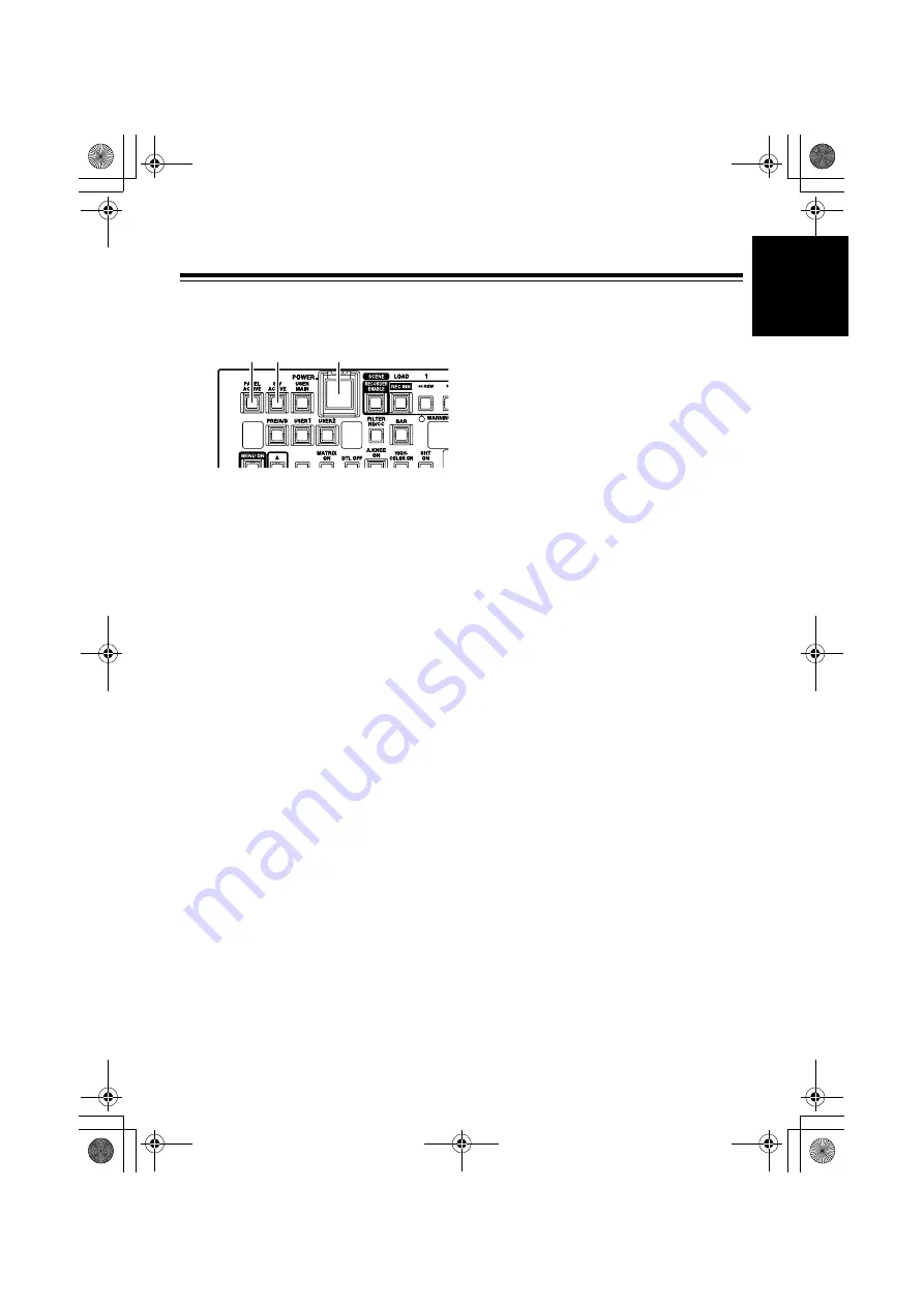
!1"

POWER button

ON/OFF switch of the main power supply of 
the main unit

!2"

PANEL ACTIVE button

For controlling which panel operations are 
available

When the lamp is on:

The panel operations are available. 
When the power is on, the unit is on.

When the lamp is off:

Only the POWER button and the PANEL 
ACTIVE button are available; all other 
button operations are disabled.

Turning on the self-lighting buttons and the 
LED display, which indicate the operating 
conditions of the camera recorder, follow the 
operating conditions of the camera recorder.

!3"

SW ACTIVE button

For enabling button/switch operations

When the lamp is on:

The button/switch operations are 
enabled.

When the lamp is off:

Only the POWER button, PANEL 
ACTIVE button, SW ACTIVE button, VR 
ACTICVE button, AUTO IRIS button, 
M.PED volume, and IRIS volume are 
available; all other operations are 
disabled.

Turning on the self-lighting SW and the LED 
display, which indicate the operating 
conditions of the camera recorder, follow the 
operating conditions of the camera recorder.

!1"

!2" !3"

AJ-RC10G.book  6 ページ  2006年7月26日 水曜日 午前9時25分

Summary of Contents for AJ-RC10

Page 1: ... ce manuel pour une utilisation ultérieure Prima di utilizzare questo prodotto leggere attentamente le istruzioni di questo manuale e conservarlo per riferimento futuro Antes de poner este producto en funcionamiento lea atentamente las instrucciones y conserve este manual para uso futuro 使用本产品前 请仔细阅读本说明书 并妥善保存以备日后参考 お買い上げいただき まことにありがとうございました この取扱説明書をよくお読みの上 正しくお使いください 特に 安全上のご注意 は ご使用前に必ずお読みいただき 安...

Page 2: ...ASHING LIQUIDS AND DO NOT PLACE ANY LIQUID CONTAINERS ON TOP OF THE EQUIPMENT CAUTION In order to maintain adequate ventilation do not install or place this unit in a bookcase built in cabinet or any other confined space To prevent risk of electric shock or fire hazard due to overheating ensure that curtains and any other materials do not obstruct the ventilation Note The rating plate is on the un...

Page 3: ...ure continued FCC emission limit compliance the user must use only shielded interface cables when connecting to external units Also any unauthorized changes or modifications to this equipment could void the user s authority to operate it The lightning flash with arrowhead symbol within an equilateral triangle is intended to alert the user to the presence of uninsulated dangerous voltage within the...

Page 4: ...ng 20 Saving Loading of scene files onto the SD memory card 21 Handling methods for the SD memory card 21 To load data from the card 21 To write data on the card 22 To delete files from the card 22 Initialization of the card 22 Menu operation 23 Operations using the LCD panel 23 Operation of the camera recorder menu 23 Adjustment of functions on the unit 23 Menu item 24 Menu 24 BLACK 24 FLARE 25 G...

Page 5: ...r can be controlled directly through the VTR operation switch In addition recording can be disabled using a switch z Frequently used menus can be set by accessing the menus on the LCD panel of the unit It is also possible to display the time code on the LCD panel z Down converted images with characters are output from the VIDEO OUT connector The menus can be operated on the main unit of the camera...

Page 6: ...gs for FUNC on the menu determine whether the camera recorder s settings which are adjusted when the unit is connected are returned to the settings before connecting the unit or to the state after adjustment when the unit is disconnected from the camera recorder z Do not forcefully pull the connected cable When the camera recorder is used while it is being moved the cable must be fixed to the trip...

Page 7: ...he LED display which indicate the operating conditions of the camera recorder follow the operating conditions of the camera recorder 3 SW ACTIVE button For enabling button switch operations When the lamp is on The button switch operations are enabled When the lamp is off Only the POWER button PANEL ACTIVE button SW ACTIVE button VR ACTICVE button AUTO IRIS button M PED volume and IRIS volume are a...

Page 8: ...REW button on the camera recorder and the lamp is on when a tape is rewinding In the scene file mode 1 is selected as the number for the scene file to be saved or loaded 4 FF 2 button In recorder mode This button is operated in the same way as the FF button on the camera recorder and the lamp is on when a tape is fast forwarding In scene file mode 2 is selected as the number for the scene file to ...

Page 9: ...start stop button for recording This button is operated in the same way as the REC START button on the camera recorder and the lamp is on during recording In scene file mode This button is operated in the same way as the SAVE button for scene data The current data are stored in the file on the remote controller which is selected by using the buttons from 3 to 7 9 RECORDER WARNING lamp This lamp fl...

Page 10: ...e will switch to PRE A B PRE step by step every time the button is pressed When the power is turned on the unit is in the state it was before turning off the power 5 PRE A B display This displays the WHITE BAL selection on the camera recorder using P A b 6 FILTER ND CC button This switches the FILTER display on the CC ND display 7 between ND filter and the CC filter alternately 7 CC ND Display Thi...

Page 11: ...essed the camera recorder starts the AWB Auto White Balance operation When this button is pressed during AWB operation the AWB operation will forcibly terminate The lamp is on during AWB operation and off when the operation is completed correctly If AWB operation finishes incorrectly the lamp will flash for 5 seconds and then turn off 13 ABB button When this button is pressed the camera recorder s...

Page 12: ...KNEE function ON OFF If the AUTO KNEE SW is set to OFF in the menu of the camera recorder it is impossible to turn it ON using this button When the power is turned on the unit is in the state it was before turning off the power The lamp is on when the AUTO KNEE function is ON otherwise the lamp is off 17 HIGH COLOR ON button This button switches the HIGH COLOR function ON OFF Even if the HIGH COLO...

Page 13: ...in the relative value mode It is possible to select either Flare or Pedestal for item adjustment in the Menu BLACK VR CONTROL item on the unit The operations for the G BLACK volume and B BLACK volume are the same 5 G BLACK volume This adjusts the Gch black level 6 B BLACK volume This adjusts the Bch black level 7 M PED volume This adjusts the master pedestal level The adjustment range is between t...

Page 14: ...e the button is pressed 6 FLARE lamp This lamp is on when FLARE is selected on the LCD panel 7 MATRIX lamp This lamp is on when MATRIX is selected on the LCD panel 8 GAMMA DTL button This selects the large item displayed on the LCD panel The display will switch to GAMMA DTL before entering the menu mode GAMMA step by step every time the button is pressed 9 GAMMA lamp This lamp is on when GAMMA is ...

Page 15: ...button is released 22 MENU ON button To open the menu on the camera recorder press this button continuously for 3 seconds In this case a message CAMERA MENU OPEN is displayed on the LCD panel The lamp is on at this time and operations of the menu and the scene file on the unit are not available If this button is pressed when the menu of the camera recorder is open the menu will close 23 CHARA ON b...

Page 16: ... the VIDEO signals 5 Level adjustment volume This adjusts the level of the VIDEO signals 6 Covering screw The unit can be used when the four screws are removed However do not leave the unit without these screws for long periods of time When the screws are not in use they must be stored safely Note Do not remove the four screws on the back panel 2 1 VIDEO OUT CAM RCU 50m 10m CABLE FREQUENCY LEVEL 4...

Page 17: ...n the lamp of the RECORDER ENABLE button by pressing the button and then operate the buttons of PLAY FF or REW To record signals operate the REC S S button 3 To display numerical values on the LCD panel The GAIN volume is displayed when the power is on If the button operations are enabled it is possible to switch the displayed GAIN volume BLACK volume a numerical value for M PED TC step by step by...

Page 18: ...itch on the camera recorder Functions of the USER switch can be set and confirmed on the camera menu or the USER SW item on the unit menu 3 Operation of the ABB AWB BAR switch The ABB button and the AWB button function the same as the switch for the white balance black balance of the camera recorder The lamp is on when the unit is operated If the button is pressed again during operation the lamp w...

Page 19: ...if the AWB OFFSET is set to OFF while the GAIN set value is retained if the AWB OFFSET is set to ON When the relative value mode and the absolute value mode are switched the lamp of the VR ACTIVE button turns off and the volume operation is disabled The GAIN value is unchanged 2 BLACK volume This functions as an adjustment volume for the flare FLR or the pedestal PED selected in the BLACK VR CONTR...

Page 20: ... scene files are operated using the seven buttons on the top right side of the unit Storing Select a file number to store using buttons 1 to 5 blue letters When the button is pressed the button lamp will flash If the SAVE blue letters button is pressed in this state the SAVE button lamp will also flash To store the file press the SAVE button again When the store operation is finished the lamp of t...

Page 21: ...urn off the power when a scene file is being stored Otherwise data in the scene file may be corupted Reference It is possible to adjust the scene file setting of the unit to the same state as the factory setting for the camera recorder using the following procedure However the settings that cannot be set with the unit cannot be set to the same state 1 Set the settings for the camera recorder to th...

Page 22: ... selected using the SHUTTER SYSTEM button the indication CARD RD is displayed on the LCD panel together with the value displayed under the indication and the title next to the indication 2 Select the file to read out by changing the numerical value in the Rotary Encoder 1 If there is no applicable file the indication NO FILE is displayed on the LCD panel 3 Press the Rotary Encoder 3 When the indic...

Page 23: ...mp turns off and the indication OK is displayed on the LCD panel To delete files from the card 1 Select SYSTEM using the SHUTTER SYSTEM button and display the menu on the third layer using the 4button 2 When the indication CARD DEL is displayed on the LCD panel together with the file number displayed under the indication turn the Rotary Encoder 1 to select the file to be deleted 3 When the Rotary ...

Page 24: ...ncoder3 5 When the camera menu is open the menu displayed on the LCD panel of the unit is closed CAMERA MENU OPEN is displayed Operation of the camera recorder menu With the unit it is possible to set the menu of the camera recorder by checking the monitor Use this feature to set any items that are not included in the unit menu 1 Connect the VIDEO OUT connector of the unit to the monitor 2 Press t...

Page 25: ...CK VR CONTROL and the lamp of the VR ACTIVE button is on or ABS absolute value is selected in the BLACK VR MODE item it is impossible to adjust the PRED GPEG BPEG items using the rotary encoder Adjust these items using the BLACK volume is the factory setting mode Layer Item Variable range Contents description Storage 1 RPED 100 100 To set the pedestal for Rch Yes GPED 100 100 To set the pedestal f...

Page 26: ...R 100 100 To set the flare for Bch Yes 2 FLAR CORRECT ON OFF To set ON OFF of the flare correction Yes Layer Item Variable range Contents description Storage 1 RGAM 15 15 To set the gamma for Rch Yes MGAM 0 30 0 75 To set the master gamma Yes BGAM 15 15 To set the gamma for Bch Yes 2 GAMMA MODE SEL HD SD F LIKE1 F LIKE2 F LIKE3 To select the gamma Yes 3 GAMMA CORRECT ON OFF To set ON OFF of the ga...

Page 27: ...the GAIN OFFSET of the AWB A will not be reset OFF When the AWB is executed the set value for the GAIN OFFSET of the AWB A will be reset Yes Layer Item Variable range Contents description Storage 9 AWB B MEM To set the position of the WHITE BAL switch and the assignment of Bch MEM This assigns the memory value when the AWB is executed Yes TEMP B 2300k 8000k To set the position of the WHITE BAL swi...

Page 28: ... 80 107 To set the position of the AUTO KNEE POINT by 1 step Yes AKLV 100 109 To set the AUTO KNEE LEVEL AKRESP 1 8 To set the AUTO KNEE response speed Layer Item Variable range Contents description Storage 1 MODE FIX S S To select whether the shutter setting for SHUTTER ON is set to the fixed mode or the synchro scan mode FIX Fixed shutter S S Syncro scan Yes SPED 1 60 1 100 1 120 1 250 1 1000 1 ...

Page 29: ...ing 7 HSAW W B 255 255 To adjust the B H SAW white shading Yes HPAR W B 255 255 To adjust the B H PARA white shading 8 VSAW W B 255 255 To adjust the B V SAW white shading Yes VPAR W B 255 255 To adjust the B V PARA white shading Layer Item Variable range Contents description Storage 1 TABL A B To select the table for the matrix color correction in case of the MATRIX ON and one to be set on the un...

Page 30: ...tem Variable range Contents description Storage 1 S DTL OFF A B AB To select the skin tone table that enables skin tone details OFF To select OFF of the skin color DTL A To put DTL in the SKINTONE setting set in Table A B To put DTL in the SKINTONE setting set in Table B AB To put DTL in the SKINTONE setting set in Tables A and B Yes OUTPUT MONI VIDEO To select the output that adds SKINZEBRA SZEB ...

Page 31: ...LVL 0 100 To set the target value of the auto iris Yes PEAK AVE 0 100 To determine the accounting ratio of the peak against the standard of the auto iris 2 IRIS WINDOW NORM1 NORM2 CENTER To select the auto iris detection window NORM1 Center of the screen NORM2 Bottom side of the screen CENTR Spots at the center of the screen Yes 3 IRISGAIN CAM LENS To select whether the iris gain is adjusted on th...

Page 32: ...o read out the title applied to the data of the file to be read out and display it 2 CARD WRITE 1 8 To select the file number to be written No TITLE To enter the title applied to the data of the file to be written 3 CARD DELETE 1 8 To select the file number to be deleted No TITLE To read the title applied to the data of the file to be deleted and display it 4 CARD CONFIG To configure the card No 5...

Page 33: ...l line of the 10 pin cable Attenuation of the coaxial cable must be set to around 6 dB at maximum in 10 MHz Confirmation of software version The software version for this unit can be confirmed in VERSION under SYSTEM in the unit menu Confirm for questions 1 2 3 4 5 6 7 8 9 10 1 2 3 4 5 6 7 8 9 10 Camera recorder side HR10A 10P 10P Hirose Electric Controller side HR10A 10P10S Hirose Electric Twiste...

Page 34: ...ure 0 C to 40 C 32 F to 104 F Storage temperature 20 C to 60 C 4 F to 140 F Maximum cable length 50 m Input Output CAMERA 10 pin multi connector a 1 MONITOR BNC a 1 1 VP P for menu setting Please note that specifications and appearance are subject to change for improvement purpose without notice Power supply DC 12 V Power consumption 6 W AJ RC10G book 33 ページ 2006年7月26日 水曜日 午前9時25分 ...

Page 35: ...e valuable resources and prevent any potential negative effects on human health and the environment which could otherwise arise from inappropriate waste handling Please contact your local authority for further details of your nearest designated collection point Penalties may be applicable for incorrect disposal of this waste in accordance with national legislation For business users in the Europea...

Page 36: ...rders 800 334 4881 TECHNICAL SUPPORT Emergency 24 Hour Service 800 222 0741 Panasonic Canada Inc 5770 Ambler Drive Mississauga Ontario L4W 2T3 905 624 5010 Panasonic de Mexico S A de C V Av angel Urraza Num 1209 Col de Valle 03100 Mexico D F 52 1 951 2127 Panasonic Puerto Rico Inc San Gabriel Industrial Park 65th Infantry Ave Km 9 5 Carolina Puerto Rico 00630 787 750 4300 松下電器産業株式会社 システム事業グループ 571...

Reviews: