


ELE-16
< VTR >
4. VTR SYSCON
4-1. Initial Setting of DIP SW
(Release Data Saving Prohibition)
1. Turn OFF the power supply of main unit and set
the DIP SW on the VTR SYSCON P.C.Board as
shown below.
SW6500-2pin (SW500) : OFF
®
ON
2. Be sure to perform this setting at the first step of
entire processes to change adjustment value with
internal menu on VTR (VTR SERVICE MENU).
3. If this SW is set to the “OFF” position, the
adjustment value won’t be saved to EEPROM.
4. Under data saving prohibit mode, if a page in VTR
SERVICE MENU is opened, “INH” (Meaning of
INHIBIT) mark is displayed on the upper right of the
monitor screen of SDI OUT.
5. POWER
5-1. Confirmation of the Voltage
Item
TP
SPEC.
2.7V confirmation
TP6
2.75+/-0.1V
3.0V confirmation
TP2
3.15+/-0.1V
3.6V confirmation
TP7
3.6+/-0.1V
5.0V confirmation
TP10
5.0+/-0.1V
5.6V confirmation
TP8
5.65+/-0.10V
9.0V confirmation
TP13
9.05+/-0.10V
-5.0V confirmation
TP11
-5.15+/-0.10V
13.0V confirmation
TP4
13.1+/-0.2V
-13.0V confirmation
TP5
-13.1+/-0.2V
48.0V confirmation
TP3
48.0+/-4.0V
17.0V confirmation
TP14
15.30+/-0.40V
-11.0V confirmation
TP15
-10.50+/-0.40V
GND : TG1 (VTR MOTHER P.C.Board)
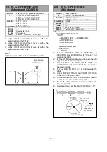
6. SERVO
6-1. T and S Reel Torque Offset
Adjustment
BOARD
SERVO
TP
TP302 (T Reel), TP301 (S Reel), TG300
(GND)
ADJUST
VR501 (T Reel), VR502 (S Reel)
MODE
Adjustment Mode
M. EQ
Digital Volt Meter
SPEC.
27 mV +/- 2 mV
< Menu >
*** VTR SERVICE MENU ***
<VTR SERVICE 2/3>
Þ
T TORQUE
Þ
S TORQUE
< T Reel Torque Offset Adjustment >
1. Without inserting a tape, perform carriage-down
then open the MENU and select the T-reel torque
adjusting mode. (When the adjusting mode is
selected the automatic loading process starts and
the T-reel rotates.)
2. Lock the T reel motor by hand and adjust VR501
so that the voltage of TP302 is within the
specification.
< S Reel Torque Offset Adjustment >
3. Without inserting a tape, perform carriage-down
then open the MENU and select the S-reel torque
adjusting mode. (When the adjusting mode is
selected, the automatic loading process starts and
the T-reel rotates.)
4. Lock the T reel motor by hand and adjust VR502
so that the voltage of TP301 is within the
specification.
5. After adjustment, disengage the adjusting mode.
< Note >
After adjusting T/S Reel Torque, turn OFF/ON the
power supply.
Summary of Contents for AJ-HDC27VP
Page 3: ... 3 ...
Page 4: ... 4 ...
Page 6: ... 6 ...
Page 7: ...Printed in Japan FCD0108NCKK71 ...
Page 136: ...ELE 25 9 TP VR and SW Location AUDIO LCD P C BOARD VEP84331B COMPONENT SIDE FOIL SIDE ...
Page 137: ...ELE 26 VIDEO OUT P C BOARD VEP23500B VTR SYSCON P C BOARD VEP86303C COMPONENT SIDE FOIL SIDE ...
Page 138: ...ELE 27 SERVO P C BOARD VEP82224B COMPONENT SIDE FOIL SIDE ...
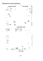
Page 139: ...ELE 28 VIDEO MAIN P C BOARD VEP83462C COMPONENT SIDE FOIL SIDE ...
Page 140: ...ELE 29 FOIL SIDE DSP MAIN P C BOARD VEP23530B COMPONENT SIDE ...
Page 141: ...ELE 30 VTR MOTHER P C BOARD VEP80B10A RF EQ P C BOARD VEP87104B COMPONENT SIDE COMPONENT SIDE ...
Page 151: ...HEAD BUFFER BLOCK DIAGRAM BLK 6 ...
Page 152: ...BLK 7 RF EQ BLOCK DIAGRAM ...
Page 153: ...HD SDI TX VIDEO MAIN BLOCK DIAGRAM BLK 8 DSP MAIN DSP MAIN DSP MAIN DSP MAIN HD SDI TX ...
Page 155: ...SERVO BLOCK DIAGRAM BLK 10 ...
Page 157: ...VTR SYSCON SD CARD BLOCK DIAGRAM BLK 12 Q1 SD CARD CKK USED USED ...
Page 158: ...POWER MAIN SUB BLOCK DIAGRAM BLK 13 ...
Page 323: ...PRT 2 MECHANICAL CHASSIS ASSEMBLY 1 ...
Page 325: ...PRT 4 MECHANICAL CHASSIS ASSEMBLY 2 ...
Page 327: ...PRT 6 CHASSIS FRAME ASSEMBLY 1 ...
Page 329: ...PRT 8 CHASSIS FRAME ASSEMBLY 2 ...
Page 331: ...PRT 10 CHASSIS FRAME ASSEMBLY 3 ...
Page 333: ...PRT 12 CASSETTE COMPARTMENT ASSEMBLY ...
Page 335: ...PRT 14 PACKING PARTS ASSEMBLY ...
Page 387: ...HEAD BUFFER BLOCK DIAGRAM BLK 6 ...
Page 388: ...BLK 7 RF EQ BLOCK DIAGRAM ...
Page 389: ...HD SDI TX VIDEO MAIN BLOCK DIAGRAM BLK 8 DSP MAIN DSP MAIN DSP MAIN DSP MAIN HD SDI TX ...
Page 391: ...SERVO BLOCK DIAGRAM BLK 10 ...
Page 393: ...VTR SYSCON SD CARD BLOCK DIAGRAM BLK 12 Q1 SD CARD CKK USED USED ...
Page 394: ...POWER MAIN SUB BLOCK DIAGRAM BLK 13 ...
Page 399: ...CBA 5 FOIL SIDE CCD SENSOR P C BOARD VEP20854A FOIL SIDE IC101 E1 IC201 C1 IC301 A1 ...
Page 499: ...ELE 25 9 TP VR and SW Location AUDIO LCD P C BOARD VEP84331B COMPONENT SIDE FOIL SIDE ...
Page 500: ...ELE 26 VIDEO OUT P C BOARD VEP23500B VTR SYSCON P C BOARD VEP86303C COMPONENT SIDE FOIL SIDE ...
Page 501: ...ELE 27 SERVO P C BOARD VEP82224B COMPONENT SIDE FOIL SIDE ...
Page 502: ...ELE 28 VIDEO MAIN P C BOARD VEP83462C COMPONENT SIDE FOIL SIDE ...
Page 503: ...ELE 29 FOIL SIDE DSP MAIN P C BOARD VEP23530B COMPONENT SIDE ...
Page 504: ...ELE 30 VTR MOTHER P C BOARD VEP80B10A RF EQ P C BOARD VEP87104B COMPONENT SIDE COMPONENT SIDE ...
Page 554: ...PRT 2 MECHANICAL CHASSIS ASSEMBLY 1 ...
Page 556: ...PRT 4 MECHANICAL CHASSIS ASSEMBLY 2 ...
Page 558: ...PRT 6 CHASSIS FRAME ASSEMBLY 1 ...
Page 560: ...PRT 8 CHASSIS FRAME ASSEMBLY 2 ...
Page 562: ...PRT 10 CHASSIS FRAME ASSEMBLY 3 ...
Page 564: ...PRT 12 CASSETTE COMPARTMENT ASSEMBLY ...
Page 566: ...PRT 14 PACKING PARTS ASSEMBLY ...


