background image

– 101 –

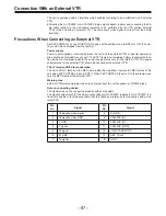
Setting Menu Screens

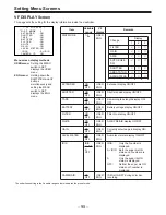
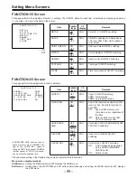
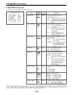
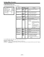
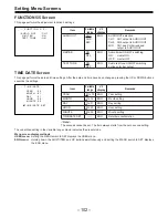
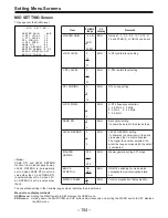
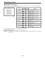
FUNCTION 4/5 Screen

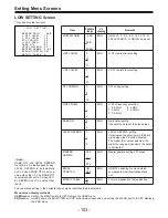
This page performs the adjustment function 4 settings.

The underlined setting in the Variable range column indicates the preset mode.

Menu screen display methods
USER menu: 
Setting the MENU switch to SET displays the USER menu.
ENG menu:

Holding down the SHIFT/ITEM and UP buttons simultaneously and setting the MENU switch to SET displays
the ENG menu.

Item

FRONT MIC

REAR MIC CH1

REAR MIC CH2

LINE CH1/CH2

REAR AUDIO

MIC LOWCUT
CH1

MIC LOWCUT
CH2

EMPHASIS

CUE AUDIO

Variable

range

p

40/

p

50

/

p

60 dB

p

40/

p

50/

p

60 dB

p

40

/

p

50

/

p

60 dB

o

4/0/

p

6 dB

STEREO

MONO

ON
OFF

ON
OFF

ON
OFF

CH1
CH2
MIX

VF

display

ENG

ENG

ENG

ENG

ENG

ENG

ENG

ENG

ENG

Remarks

Camera microphone input level
selection

Rear jack AUDIO CH1 input
microphone level selection

Rear jack AUDIO CH2 input
microphone level selection

Rear jack AUDIO CH1/CH2 input line
input level selection

Audio CH1/CH2 rear jack input
selection
STEREO:

Selects stereo input (CH1
input is recorded in CH1
and CH2 input is recorded
in CH2.)

MONO:

Selects monaural input
(The signals of CH1 and
CH2 are mixed and
recorded in CH1 and CH2
respectively.)

CH1 microphone bypass filter ON/OFF
switching

CH2 microphone bypass filter ON/OFF
switching

Emphasis ON/OFF switching

CUE AUDIO recording setting
CH1: Records CH1 AUDIO
CH2: Records CH2 AUDIO
MIX: Records CH1 and CH2 mixed

AUDIO.

- FUNCT I ON 4 / 5 -

¢

FRONT M I C

: - 4 0 d B

REAR M I C CH 1

: - 6 0 d B

REAR M I C CH 2

: - 6 0 d B

L I NE CH 1 / CH 2

: + 4 d B

REAR AUD I O

: S T EREO

M I C L OWCUT CH 1 : OF F
M I C

L OWCUT CH 2 : OF F

EMPHAS I S

: OF F

CUE AUD I O

: CH 1

Summary of Contents for AJ-D400P

Page 1: ...ocedures Mechanical Adjustment Sec 4 Electrical Adjustment Sec 5 Block Diagrams 1999 Matsushita Electric Industrial Co Ltd All rights reserved Unauthorized copying and distribution is a violation of law Vol 1 Please refer to the Service Manual Volume2 Order No VSD9903M004B for Schematic Diagrams Circuit Board diagrams and Exploded Views Parts List ...

Page 2: ...Printed in Japan F37309903NCKD222 ...

Page 3: ...ADJ MENU SCREEN 2 2 VTR D A DATA MENU SCREEN 2 3 BATTERY SETTING MENU SCREEN 2 4 WHITE SHADING MENU SCREEN 2 5 2 Design Menu Screen 2 6 How to reset the HOUR METER 2 7 HOUR METER RESET MENU SCREEN 2 7 SBC OPTION MENU SCREEN 2 8 3 Option Menu Screen 2 9 How open the Option Menu 2 9 Auto off Information 2 10 ...

Page 4: ...on menu screen only Table of Setting Menu User Engineer Service Design Option MAKER VF DISPLAY CAMERA ID SHUTTER SPEED SYNCRO SCAN LED SET UP CARD AJ D700 only MAIN FUNCTION BATT TAPE ARARM FUNCTION 1 5 FUNCTION 2 5 FUNCTION 3 5 FUNCTION 4 5 FUNCTION 5 5 TIME DATE LOW SETTING MID SETTING HIGH SETTING LEVEL 1 6 LEVEL 2 6 LEVEL 3 6 LEVEL 4 6 LEVEL 5 6 LEVEL 6 6 VF OPERATION LENS ADJ MENU SELECT 1 3 ...

Page 5: ...ow to use SERVICE ADJ MENU SCREEN SERVICE ADJ GAMMA SERV ON R GAMMA SERV B GAMMA SERV TEST PULSE OFF ECU CONNECT ECU CONCEAL ON INNER ECC ON OUTER ECC ON IF ADJ OFF SERVO MODE ATF This menu sets the modes for servicing ITEM RANGE PRESET REMARK GAMMA SERV ON OFF ON GAMMA setting become effective R GAMMA SERV 10 10 Setting of Rch GAMMA B GAMMA SERV 10 10 Setting of Bch GAMMA TEST PULSE ON OFF OFF TE...

Page 6: ...stment P C Board 01 SYNC_LEVEL V_MAIN 13 Pr_CLAMP_DC V_I F 02 Y_LEVEL V_MAIN 14 TEST_4 V_I F 03 C_LEVEL V_MAIN 15 TEST_3 V_I F 04 FS_12 V_MAIN 16 C_LEVEL V_I F 05 17 Y_LEVEL V_I F 06 18 07 EQ_A_L RF 19 HUE V_I F 08 EQ_A_R RF 1A OUT_BIAS V_I F 09 EQ_B_L RF 1B PLL_POSITION V_I F 0A EQ_B_R RF 1C APC V_I F 0B PLL_VCO RF 1D NOT_ADJ_L V_I F 0C ATF_GAIN RF 1E REC_FREQ_L RF 0D PLL_SLICE RF 1F REC_FREQ_R R...

Page 7: ...AUTO AUTO The warning voltage for timing of BATTERY BEFORE END follow the type of Battery as indicated as below Battery type is selected by item BATTERY SELECT on FUNCTION 3 5 menu screen Ni Cd 12V 11 5V Ni Cd 13V 12 8V Ni Cd 14V 13 9V MAMUAL The detected voltage of BATTERY BEFORE END follows the value of below setting BATTERY BEFORE END 11 0V 14 0V 11 3V Adjusted by 0 1V step ...

Page 8: ... WHITE SHADING MENU SCREEN WHITE SHADING WHITE DIGITAL AUTO WHITE SHADING can be executed ITEM RANGE PRESET REMARK WHITE DIGITAL Execute the Auto White Shading Digital ...

Page 9: ...N H F COMP ON MENU ALL INIT Y C TIMING 1 SCH 4 DEFECT MODE ON STATUS OFF NOTE Please be carefully press UP or DOWN button by mistake when select the item MENU ALL INIT Then reset all data on all menus except value of FLARE and GAMMA ITEM RANGE PRESET REMARK H F COMP ON OFF ON It compensates for the input signal high pass frequency component MENU ALL INIT Reset all data on all menu refer to above s...

Page 10: ...urs and Threading Times can be reset by using HOUR METER RESET menu screen How to reset After select the item press UP or DOWN button and then execute reset function HOUR METER RESET MENU SCREEN HOUR METER RESET DRUM RUNNING RESET THREADING RESET ITEM RANGE PRESET REMARK DRUM RUNNING RESET Reset of Drum Running hours THREADING RESET Reset of loading times ...

Page 11: ... 0 0 0 0 0 0 0 40 0 0 0 0 0 0 0 0 0 0 0 0 0 0 0 0 0 0 0 0 50 0 0 0 0 0 0 0 0 0 0 0 0 0 0 0 0 0 0 0 0 60 0 0 0 0 0 0 0 0 0 0 0 0 0 0 0 0 0 0 0 0 70 0 0 0 0 0 0 0 0 0 0 0 0 0 0 0 0 0 0 0 0 80 0 0 0 0 0 0 0 0 0 0 0 0 0 0 0 0 0 0 0 0 90 0 0 0 0 0 0 0 0 0 0 0 0 0 0 0 0 0 0 0 0 The data which are recorded in SBC OPTION area on the tape are displayed ITEM RANGE PRESET REMARK SBC OPTION Display only ...

Page 12: ...FRONT ALL The TEST TONE signal is output when the CAM BAR switch is set to BAR METER SELECT CH1 BOTH CH1 CH1 Audio LEVEL METER which is displayed on the View Finder is displayed only CH1 BOTH It displayed both CH1 and Ch2 VF DISPLAY NORMAL SPECIAL NORMAL NORMAL Status always displayed SPECIAL Status displayed only MODE CHECK SW set to ON TC OUT TCG TCG TCR TCG TCG TCG signal always output TCG TCR ...

Page 13: ...e isn t released Drive circuit P605 S P608 T 3 Cassette is not loaded correctly on a reel 4 Tape is stacked to drum 0D Capstan The condition that FG frequency is less than half or more than twice of specification lasts more than 1 5 seconds 1 Capstan doesn t rotate Drive circuit P616 2 No capstan FG P616 1 and 3 0E Cylinder The condition that FG frequency is less than half or more than twice of sp...

Page 14: ...0 Emergency Eject 3 22 11 Cleaning Procedures 3 23 11 1 Cleaning of Head Chips Daily 3 23 11 2 Cleaning of Drum Lead Weekly 3 23 11 3 Cleaning of A C Head Weekly 3 23 11 4 Cleaning of Pinch Roller and Capstan Weekly 3 23 11 5 Cleaning of Post Weekly 3 23 12 Mechanical Parts Replacement and Adjustment Procedures 3 24 12 1 Drum Unit Replacement 3 24 12 1 1 Adjustment Flow Chart After Drum Unit Repla...

Page 15: ... Adjustment 3 51 1 10 REV Tension Confirmation 3 52 1 11 Tension Confirmation 3 53 1 12 Tape Pass Adjustment Procedure 3 54 1 13 Envelope Waveform Adjustment 3 55 1 14 Post Limit Confirmation PLAY 3 56 1 15 A C Head Adjustment Method 3 57 1 16 A C Head Tilt Adjustment 3 58 1 17 A C Head Height Adjustment 3 59 1 18 A C Head Azimuth Adjustment 3 60 1 19 A C Head Tilt Confirmation 3 61 1 20 A C Head ...

Page 16: ...crew Unit VXQ0556 9 Mech Chassis Unit VXY1308 10 1 5 CRT EVF M04KYS07WB Replace the CRT at each 5 000 hours Operation Time Note Hours of Use are based on the head rotation hours Hours of Use are recommendation It may depend on temperature humidity or dusty Hours of Use are listed as the reference of maintenance They do not mean guarantee hours Symbol Maintenance Remark Replacement Replacement Thes...

Page 17: ...nit Mode SW U Main Cam Gear Pinch Arm U T Reel Motor U REC Inhibit SW Distinction SW U T Reel Brake Arm Unit S Reel Brake Arm Unit Cleaner Solenoid S Post Base AU S1 Leading Arm U Tension Arm AU Cleaner Arm U T1 Boat U M Cassette Break T AU M Cassette Break S AU S Reel Motor U ...

Page 18: ...s yes 24 VFK1190 HEX Wrench yes yes 25 VFK1209 Torque Driver 0 4 3Kg yes yes 26 VFK1375 Post Axis Driver 1 5mm yes yes Instead of VFK0912 27 VFK1300 A D Board DAQ 12 Quatech yes yes Purchase locally 28 VFM3580KM Alignment Tape No 1 NTSC yes yes 29 VFM3581KM Alignment Tape No 2 NTSC yes yes 30 VFM3582KM Alignment Tape No 3 NTSC yes yes 31 AJ CL12MP Cleaning Tape yes yes SALES 32 VFK1481 LISTA Softw...

Page 19: ...K1208 Neutral Black With hole Gold Black 13 VFK1150 Nut Driver 5 5mm 14 VFK1151 Nut Driver 2 5mm 15 VFK1188 30g Dial Tension Gauge 16 VFK0948 or purchase locally Check Light 17 VFK0749 Froiral Grease White for plastic part 18 MOR265 Morlytone Grease Black for metal part 19 VFK1146 00 x 75 20 VFK1147 0 x 100 Philips Driver 21 VFK1148 1 5mm 22 VFK1178 0 89mm 23 VFK1179 0 71mm Hex Driver 24 VFK1190 1...

Page 20: ...R Counter Tool 39 VFK1185 B E R Counter Cable 40 VFKW1000AA EVR I F Box Unit 41 VFKW1000C EVR RS232C Cable 42 VFK1180 EVR SUB I F Unit 43 VFK1187 EVR Cable 44 VFK1210 Multi Canon Cable 45 VFK0369 Tweezers 46 VFK0371 Radio Prier 47 VFK0372 Cutter Prier 48 VFK0338 Trimmer Adjustment Driver 49 VFK0337 Philips Driver 50 VFK1423 Tape Big End Det Cassette 51 VFM3680KM 52 VFM3681KM 53 VFM3682KM F H Use f...

Page 21: ...OP SC or 1780R Waveform Vector Monitor TEKTRONIX Digital Volt Meter Frequency Counter VTVM Distortion Meter CR Oscillator PAL Part No Name Remark TSG131A OP 04 Analog Component Signal Generator TEKTRONIX Oscilloscope TEKTRONIX 1751 OP SC or 1781R Waveform Vector Monitor TEKTRONIX Digital Volt Meter Frequency Counter VTVM Distortion Meter CR Oscillator ...

Page 22: ...5 Boards Location ...

Page 23: ... Area Markers 50Hz 15kHz Response VFM3581KM NTSC VFM3582KM NTSC Time min Signal Time min Signal 0 00 20 00 ITI Pattern 0 00 10 00 X Value VFM3680KM PAL Time Video PCM CUE min Signal Purpose Signal Purpose Signal Purpose 0 00 Color Bar 100 Video Level Confirmation 1kHz Reference level CUE Level Confirmation 10 00 H Sweep Frequency Response 1kHz 18dBu Audio Level Confirmation 14 00 Area Markers 6kHz...

Page 24: ...eft Side Panel After removing the cassette cover according to item 7 1 loosen the 4 screws A and remove the panel 7 3 Removal of Right Side Panel Loosen the 4 screws A and remove the panel Remove the 3 screws B and disconnect the connector A then remove the Right Side Panel Screws A Screws A Screws A Connector A Screws B Screws B ...

Page 25: ...t BNC terminal and disconnect the connector G and H on the Rear Jack P C Board Disconnect the connector I on the Mother P C Board and loosen the 2 screws D and remove the 2 screws E Remove the mechanical chassis with care not to scratch the any connectors and cables Note When the mechanical chassis unit installed confirm the connector P1001 on the Rear Jack P C Board connected correctly Screws A S...

Page 26: ... figure Disconnect the connector A and the 3 screws A Remove the 2 screws and remove the T1 Guide Remove the screw B and the drum unit with care not to scratch the cable A 7 6 Removal of Cassette Up Unit After removing the left side panel according to 7 2 loosen the 4 screws A and remove the panel Cable A Screw B Screw A Connector A Screw C Screw A ...

Page 27: ... of Camera Unit After removing the both panels according to item 7 2 and 7 3 disconnect the connector A Disconnect the connector B Remove the 4 screws C and pull out the camera unit Connector A Screw C Connector B ...

Page 28: ...tape may be damaged by ejecting it the cassette tape should be ejected out by the following steps 1 Turn the power off 2 Open the rubber cap above the GEN LOCK IN connector Push in and rotate the red screw counterclockwise 3 The tape is unloaded with click 4 Continue until the cassette tape is ejected ...

Page 29: ...to touch a head chip Clean the drum lead with a pick 9 3 Cleaning of A C Head Weekly Wipe the A C head with a cloth soaked by cleaning liquid Wipe again with a dry cloth 9 4 Cleaning of Pinch Roller and Capstan Weekly Wipe the Pinch Roller and Capstan with a cloth soaked by cleaning liquid 9 5 Cleaning of Post Weekly Wind a cloth on a pick Wipe each post dry with that pick Wipe again with a dry cl...

Page 30: ...e replaced follow the replacement procedure 10 1 Drum Unit Replacement Removal 1 Remove the T1 Guide and Cleaning Arm Unit Refer to item 10 8 2 After removing the mechanical chassis according to item 11 4 disconnect the connector A and the 3 screws A Fig 10 1 Remove the screw B and the drum unit with care not to scratch the cable A Note Be careful when removing the flexible cable from the connecto...

Page 31: ...uide T1 Guide position adjustment should be performed Refer to item 10 8 1 Note When installing the Cylinder Unit the pin on Mech Chassis should match hole of Cylinder Unit as shown in Figure 10 1 3 Note Please put the flexible B and C between copper shield plate D and E as shown in Figure 10 1 5 Fig 10 1 3 Fig 10 1 5 ...

Page 32: ...cal Adj Section 3 Electrical Adj Section 4 PG SHIFTER ADJUSTMENT PB EQUALIZER ADJUSTMENT 1 PB ENVELOPE LEVEL CONFIRMATION R P ENVELOPE LEVEL CONFIRMATION HSE SIGNAL CONFIRMATION CONFIDENCE PB ENV LEVLL ADJUSTMENT REC CURR FREQ Rch ADJUSTMENT REC CURR FREQ Lch ADJUSTMENT END REV TAPE PASS CONFIRMATION ADJ LISTA CONNECTION AND BOOT UP TAPE PASS LIMIT CONFIRMATION PLAY TAPE PASS LIMIT CONFIRMATION CT...

Page 33: ...r Jack P C Board and P600 on the Servo P C Board and then remove the A C Head from the A C Head Plate Fig 10 2 1 Removal of A C Head 5 Remove 2 screws D to remove the Shield Cover as shown in Figure 10 2 3 6 Unsolder the lead wires one by one Don t unsolder all wires at the same time Installation 1 Remove the Shield Case from the New A C Head and solder the lead wires to New A C Head Refer to Figu...

Page 34: ...t 1 After replacing the A C Head perform the following steps A C Head Side Cable Color Connector No 1 PINK YELLOW 2 WHITE 3 PINK RED P1003 4 WHITE 5 PINK GREEN 6 WHITE 7 WHITE YELLOW P600 8 BLACK Section 3 START A C HEAD TILT ADJUSTMENT X VALUE ADJUSTMENT LISTA ADJUSTMENT PROCEDURE ITEM 1 31 to 1 36 A C HEAD AZIMUTH ADJUSTMENT A C HEAD HEIGHT ADJUSTMENT END CUE REC CURRENT ADJUSTMENT CUE RECORDING...

Page 35: ...3 2 8 Unscrew the 4 screws C to remove the Supply Reel Rotor Unit as shown in Figure 10 3 2 9 Unscrew the 2 screws D to remove the S Side M Stopper from Supply Reel Rotor Unit as shown in Figure 10 3 3 CAUTION Don t touch FG portion with the magnetized screw driver when unscrewing the screw D Installation 1 Install the new Supply Reel Rotor Unit according to the opposite procedures to removing 2 C...

Page 36: ...ch FG portion with the magnetized screw driver when unscrewing the screw D 6 Unscrew the 2 screws G to remove the T Side M Stopper from Take Up Reel Rotor Unit as shown in Figure 10 3 3 Installation 1 Install the new Take Up Reel Rotor Unit according to the opposite procedures to removing 2 Confirm the Main Brake Torque Refer to item 1 3 of Section 3 3 Adjust the Reel Torque Offset Refer to item 6...

Page 37: ... 2 screws C so that the pin of Mode SW Unit matches groove position of main Cam Gear 3 Install the Emergency Shaft and tighten the screw B 4 Install the Pinch Solenoid Unit After installing Pinch Solenoid Position adjustment is required Refer to item 1 2 of Section 3 10 5 Pinch Arm Unit Replacement Removal 1 Remove the Cassette Cover and Left Side Panel 2 Remove the Cassette Up Unit 3 Disconnect t...

Page 38: ...10 6 1 Removal of M Cassette Brake Base Unit 10 7 Mode Select Switch Unit Replacement Removal 1 Remove the Cassette Cover and Left Side Panel 2 Remove the Cassette Up Unit 3 Disconnect the connector P612 on the Servo P C Board as shown as Figure 10 3 1 4 Remove the Pinch Solenoid Unit and Loading Motor Neutral Unit Refer to item 10 4 5 Remove the screw D to remove the Mode Select Switch Unit from ...

Page 39: ...that the Cleaner Roller is rotated when the cylinder is rotated 4 T1 Guide position adjustment should be performed 10 8 1 T1 Guide Position Adjustment Place the unit in Loading completion mode How to Make the No Tape Loading l Set a black tube to TAPE LED sensor l Turn on the power and then the VTR begins loading without tape And turn power to off 1 Observe the clearance B between T1 Guide and T1 ...

Page 40: ...Unit 4 Unscrew 4 screws B and remove the Supply and Take up Brake Solenoid from Supply and Take up Brake Solenoid Unit 5 Lift up Supply and Take up Brake Arm Unit and hang off spring at Brake Arm Unit side Installation 2 Install the new Brake Arm Unit according to the opposite procedures to removing Fig 10 6 1 Removal of M Cassette Brake Base Unit SCREW A S BRAKE ARM U S BRAKE ARM U SCREW B ...

Page 41: ...ation 1 Install the new Pinch Solenoid according to the opposite procedures to removing 2 After installing Pinch Solenoid Position Adjustment is required Refer to item 1 2 of Section 3 Fig 10 9 1 Removal of Pinch Solenoid 10 10 MIC Base Unit Replacement Removal 1 Remove the Cassette Cover and Left Side Panel 2 Remove the Cassette Up Unit 3 Disconnect the connector P607 on Servo P C Board 4 Unscrew...

Page 42: ... 1 Installation 1 Install the new S1 Loading Arm Unit according to the opposite procedures to removing Then S1 Post Loading Arm Unit Phase Adjustment should be performed as shown below 2 Adjust S1 Post Loading Arm Unit so that the hole A should match hole B as shown in Figure 10 10 1 3 After installing confirm that the S1 Post moves smoothly on the Loading Rail 4 Tension Arm Offset Refer to item 1...

Page 43: ... Loading Arm Unit as shown in Figure 10 10 1 Installation 1 Install the T1 Loading Arm Unit according to the opposite procedures to removing Then Phase Adjustment should be performed as follows Note This unit should be replaced simultaneously with Cylinder Unit It makes Replacement of T1 Loading Arm Unit easier Adjustment 1 When installing the T1 Boat Unit the hole A should match hole B as shown i...

Page 44: ...t by moving to arrow direction C Û C with eccentric driver so that the clearance D is within specification And tighten the 2 screws A 4 After adjustment confirm as follows 5 Press the iron core of Cleaner Solenoid to release and then return the Cleaning Roller to original position 6 Press the iron core of the Cleaner Solenoid and confirm that the Cleaner Roller is rotated when the cylinder is rota...

Page 45: ...ance A is within specification And tighten the 2 screws B Fig 10 13 4 Cleaner Roller Position Adjustment 10 14 S5 Post Base Unit Replacement Removal 1 Remove the Cassette Up Unit 2 Unscrew the screw A and remove the S5 Post Base Unit as shown in Figure 10 14 1 Installation 1 Install the S5 post Base Unit according to the opposite procedures to removing 2 After installing Post Height Pre adjustment...

Page 46: ...Installation 1 Install the new Tension Arm Unit according to the opposite procedures to removing 2 After installing Tension Arm Adjustment should be performed as follows Fig 10 15 1 Removal of Tension Arm Unit Tension Arm Adjustment Flowchart START 1 6 TENSION OFFSET ADJUSTMENT 1 9 TENSION SPRING ADJUSTMENT 1 8 PLAYBACK VOLTAGE ADJUSTMENT 1 7 NEUTRAL POSITION ADJUSTMENT END 1 8 REV VOLTAGE CONFIRM...

Page 47: ...s shown in Figure 10 16 1 2 Follow the opposite procedures to removing 3 After installing Pinch Solenoid Position Adjustment is required Refer to item 1 2 of section 3 Fig 10 16 1 Removal of Main Cam Gear 10 17 T4 Post Phase Adjustment 1 Confirm that the hole B of T4 Connector Gear was matched to hole of T4 Post as shown in figure 10 17 1 2 Confirm the relation between portion C of T4 Connector Ge...

Page 48: ...apstan Rotor just starts turning separate from the Capstan Rotor 5 Turn the Thrust Adjustment Screw another an angle of 270 degree from 180 degree about 225 degree clockwise as shown in figure 10 18 1 6 Put the glue EX Three Bond 1401B on the Thrust Adjustment Screw 7 Confirm whether the Oil Seal does not come in contact with the Capstan Housing Fig 10 18 1 Location of Oil Seal and Thrust Screw Fi...

Page 49: ...1 Mechanical Adjustment Procedures TP VR location Servo P C Board TP302 VR501 TG300 TP902 TP101 VR502 TP301 TP116 TP113 TP114 TP503 TP502 TP501 TP504 TP505 VR503 VR504 VR103 VR104 VR102 VR101 TP601 TP102 TP402 VR402 VR401 TP107 ...

Page 50: ...ition at VTR 2 Push the pinch roller by hand to be close to capstan 3 Push the pinch solenoid by hand so that the pinch roller contacts capstan 4 Loosen the two screws A and adjust the hole B by VFK0357 so that gap T is within specification 5 The position for confirm Gap which is located spring scratch to Plate C side Portion A Plate D Spring Z Plate C Gap T Gap T Plate D ...

Page 51: ...ake 4 Confirm the torque is within specification 5 Put the torque gauge on T Reel and turn the torque gauge to direction A until T Reel slips against brake 6 Confirm the torque is within specification 7 Install the adapter VFK1152 to the torque gauge VFK1191 8 Put the torque gauge on S Reel and turn the torque gauge to direction B until S Reel slips against brake 9 Confirm the torque is within spe...

Page 52: ...t as shown in figure 3 Adjust the each post to Lower limit by VFK1154 as shown in figure 4 VFK1149 use for Post height adjustment of S4 and S5 post VFK1151 use for Post height adjustment of T3 and T4 post Post Limit Post Driver S5 Post Lower VFK1149 S4 Post Lower VFK1149 T3 Post Lower VFK1151 2 5mm Nut Driver T4 Post Lower VFK1151 2 5mm Nut Driver Note Lower Turn S4 and S5 posts 1 round more count...

Page 53: ...ension Adjustment Flowchart END START Neutral Position Adjustment Tension Offset Adjustment Playback Voltage Adjustment OK Rev Voltage Confirmation OK NG NG Tension Spring Adjustment Rev Tension Confirmation ...

Page 54: ...1 6 Tension Offset Adjustment BOARD SERVO SPEC 2 5 0 05V TEST POINT TP402 ADJUSTMENT VR402 MODE EJECT TOOL Digital Volt Meter 1 Adjust the VR402 so that the DC voltage at TP402 is within specification ...

Page 55: ...ect Sensor LED and press the lever P to place the unit in no tape loading mode 4 Loosen the screw A and move the lever D with tweezers for adjust the sensor position so that the DC voltage at TP402 is within specification CAUTION 1 Do not use magnetized tweezers and Screw driver 2 Do not touch the magnetize Screw driver to S Reel FG magnet portion when the lever D portion is adjusting Note Make a ...

Page 56: ...s shown in figure 2 Set the tube to cover the Tape Detect Sensor LED and press the lever P to place the unit in no tape loading mode 3 Adjust the VR401 so that the DC voltage at TP402 is within specification PLAY 4 Install the VFK1155 as shown in figure and confirm that the DC voltage at TP402 is within specification REV 5 If it out of spec perform the Neutral Position adjustment again Note Make a...

Page 57: ...nit 2 Set the tube to cover the Tape Detect Sensor LED and press the lever P to place the unit in no tape loading mode 3 Insert the tension gauge to push the tension post to the direction R until the voltage at the TP402 is 3 8V PLAY position 4 Loosen the screw C and adjust the position of hook B so that the indication of gauge is within specification Note Make a tube by yourself P Reel Brake Sole...

Page 58: ...ensor LED and press the lever P to place the unit in no tape loading mode 3 Insert the tension gauge to push the tension post to the direction R until the voltage at the TP402 is 1 2V REV position 4 Confirm that the indication of gauge is within specification If not make the Tension Spring Adjustment again 5 After finish this adjustment grew the screw A B and C The grew quantity at B is half of A ...

Page 59: ...portion of the tape 2 Insert the tension meter between S3 post and S4 post Refer to figure 3 Confirm the tension is within specification 4 Place the unit in REV mode 5 Insert the tension meter between S4 post and S5 post Refer to figure 6 Confirm the tension is within specification NOTE Be careful not to give some tape damage Play Tension Rev Tension ...

Page 60: ...ss Conf T4 Post Adj 1 23 CTL Self Recording Level Conf 1 24 PLAY Tape Pass 1 25 Conf Of Envelope REV REW and FF mode 1 26 Conf of PLAY start 1 27 REV Tape Pass 1 28 FF REW Tape Pass 1 29 Screw Lock Tight of A C Head T3 T4 Post NG NG NG NG PLAY NG REV T4 Post Adj Each Post and A C Head Adj S4 Post Conf Each Post Limit END To PG and LISTA Adj OK OK OK OK OK OK OK OK OK OK OK OK OK OK OK NG NG NG NG ...

Page 61: ...st height so that the R P envelope output is within the specification 3 When the S1 and T1 posts are adjusted first raise the post height and make small the entrance and exit side of the envelope then down the post until envelope becomes flat 4 With order to adjustment basically adjust T1 post for makes flat at exit side of envelope first and adjust S1 post 5 After finish this adjustment unload th...

Page 62: ... as below table and adjust it in case of need 2 Confirm that the kinds of D E and F condition do not appeared on the tape as shown in figure Post Limit Adjustment S5 Lower limit or Free S5 Post Height S4 Lower Limit S4 Post Height S1 Upper Limit Envelope waveform T1 Upper Limit Envelope waveform T3 Lower Limit T3 Post Height T4 Lower limit or Free T4 Post Height A UPPER B FREE C LOWER D Curl E Ben...

Page 63: ...A VFK1178 0 89mm Hex Driver B VFK1150 5 5mm Tool for adjustment F VFK1148 1 5mm Hex Driver C D G VFK1209 Torque Driver VFK0912 1 5mm Post Axis Driver H VFK1190 1 5mm L type of Hex Wrench 1 Each adjustment of A C Head should be perform under the screw G tightened 2 Confirm the screw A does not loosen before execute the A C Head Tilt adjustment The screw A should be always touch to top of A C Head 3...

Page 64: ... T3 post by screw A And tighten screw A accordingly for find the point of curl disappeared After finish adjustment for screw A tighten the screw G is tightened with 1 0Kg cm of torque NOTE 1 In case of turn clockwise screw A Tape goes up at T3 post 2 In case of turn counter clockwise screw A Tape goes down at T3 post 3 When screw adjustment finished with each adjustment screw on A C Head should be...

Page 65: ...irm that the CTL output level is decreased 3 If increases CTL output when press the A C Head Loosen the screw H and adjust the screw B counterclockwise until CTL output is maximized 4 If increases CTL output when lift up the A C Head Loosen the screw H and adjust the screw B clockwise until CTL output is maximized 5 After tightening the screw H 2 0kg confirm the level again NOTE 1 Adjust alternate...

Page 66: ...d MODE PLAY TAPE VFM3580KM VFM3680KM M EQ Oscilloscope TOOL VFK1148 Hex Driver 1 Observe the CTL output TP107 on the Servo Board 2 To adjustment loosen the screw G and adjust screw F so that the CTL output become maximum 3 Tighten screw G with 1 0Kg torque NOTE 1 Adjust alternately with other A C head adjustments Azimuth Height ...

Page 67: ...Push the tension arm follow the arrow B direction as shown in figure as range of T2 post does not move And confirm that the CUE output level is within specification 4 If out of specification loosen the screw G and adjust the screw A then tighten the screw G with 1 0kg torque 5 The final touch of the adjustment must be turned clockwise After this adjustment confirm that the screw A is not loosened ...

Page 68: ...C Head lightly as indicated as figure position then confirm that the CUE output level at TP505 does not increased 3 If increases CUE output A C Head Height adjustment performed And also confirm that the CTL output level 4 If adjust the height of A C Head Azimuth also changed Therefore adjust and confirm alternately Height and Azimuth of A C Head 5 After screw H is tightened height and tilt of A C ...

Page 69: ...envelope and select the HSW correspond with it The lack track is correspond HSW high with L ch 4 Adjust X value so that the reference of HSW and CTL trigger select the next trigger at duty 6 to 4 portion refer to below figure are match in the phase t1 To adjust X value loosen the screw C and D adjust the hole E by VFK0357 After adjustment tighten the screw C and D with 2 5Kg torque At this time ad...

Page 70: ...e maximum rotation angle is 90 degree 3 Place unit into REV X1 mode and confirm the CTL output level is become more than 75 on play mode Confirm the tape pass limit become lower limit at T3 post and the tape does not have curl at T3 and T4 post 4 However out of specification adjust T4 post height follow the Post Height Pre adjustment procedure T4 Nut adjustment direction Direction of adjustment nu...

Page 71: ...ion should be done after each screws of A C Head are fixed 1 Record the blank tape 2 Playback the recorded portion and confirm the CTL level is within specification as shown as below table on PLAY and REV X1 mode CTL Output Level C1 C2 PLAY REV 1 C1 C2 220mV C1 C2 170mV 1 PLAY NG Re confirm the A C Head height adjustment 2 REV NG Re confirm the T4 post adjustment C1 C2 ...

Page 72: ...st S4 S5 Post Post Height Pre Adj S1 post S1 Post Envelope waveform Adj T1 post T1 Post Envelope waveform Adj T3 post A C Head tilt A C Head tilt Adj T4 post T4 Post Post Height Pre Adj 1 Place unit into PLAY mode and confirm the each post limits is within specification 2 If out of specification adjust the post height follow the each adjustment procedure Refer to above table A Upper B Free C Lower...

Page 73: ... REW FF TAPE VFM3580KM VFM3680KM M EQ Oscilloscope 1 Confirm that the Envelope waveform becomes in the specification on REV REW and FF mode as refer to figure and below Waveform must be Diamond Style All the peak level must be more than 90 of maximum level V Vmax 0 9 2 If out of spec adjust S4 post height NG OK ...

Page 74: ...APE M cassette 63min Recorded tape Tape beginning portion M EQ Oscilloscope Note This adjustment must be done after Envelope Waveform Adjustment 1 Confirm that the envelope appears immediately when the mode is changed from REW to PLAY REV to PLAY FF to PLAY and Lording to PLAY mode 2 If out of spec adjust S4 post height OK NG ...

Page 75: ... Post Name Tape Limit Refer to figure A B C D E F S5 Post S4 Tension Post S1 Post T1 Post T3 Post T4 Post 1 Place unit into REV mode and confirm the each post limits is within specification 2 If out of specification adjust the post height follow the each adjustment procedure Refer to above table A Upper B Free C Lower D Curl E Bend F Drop ...

Page 76: ...n Post Name Tape Limit Refer to figure A B C D E F S5 Post S4 Tension Post S1 Post T1 Post T3 Post T4 Post 1 Place unit into FF and REV mode and confirm the each post limits is within specification 2 If out of specification adjust the post height follow the each adjustment procedure Refer to above table A Upper B Free C Lower D Curl E Bend F Drop ...

Page 77: ...1 3 of the screw 1 Fix the screw by the Lock Tight Grew after adjustment 2 Before adjustment melt the Grew Screw Lock Tight of T3 and T4 Post T3 Post T4 Post Lock tight grew quantity 1 4 of the screw 1 4 of the screw 1 After adjustment attach the lock tight grew at the Nylon nut 2 Before adjustment melt the Grew Nylon Nut Lock Tight T4 Post ...

Page 78: ...1 30 LISTA Adjustment Procedure LISTA Connection and Boot up LISTA Linearity Adjustment START END LISTA Sensitivity Adjustment LISTA Sensitivity Detection LISTA Waving Measurement ...

Page 79: ...DOS mode Install and Boot up All files on the floppy disk VFK1481 copy to created directly on PC i e C LISTA Type LISTA and press ENTER Key then boot up the LISTA software 4 Select the item DVC PRO then AJ D700 for selected model on the menu AJ D400P E D700P E is equivalent to AJ D700 5 After selected model appeared alignment tape data on the screen for select the Serial number on the alignment ta...

Page 80: ...ame for input the DATA and CHECK SUM appeared on the screen Input the numerical value in numerical order on the data sheet which are enclosed with alignment tape If input the wrong number appear the error message on the screen then confirm that the data on the sheet 5 After entry the data select 1 SELECT on the Alignment Tape menu and select the serial number of the alignment tape Alignment Tape D...

Page 81: ... Playback an alignment tape 4 Select the 6 ATF Error Signal Monitor on the main menu And than press SPACE key for executes initializes 5 Press the 0 zero key for download the ATF GAIN DATA from the unit 6 Press the ENTER key then sensitivity value as real time and waveform appears on the screen as shown in figure 7 Press the kry in PC so that the sensitivity value which is described as Sens Value ...

Page 82: ... on the Power and playback an alignment tape 3 Select the 1 Sensitivity Measurement on the main menu and after appear the message 1 2 Speed press ENTER key then LISTA software start measurement of sensitivity value 4 Confirm that the sensitivity value is within specification when the message Sensitivity Measurement Finish and Sensitivity numerical value are displayed on the screen 5 If out of spec...

Page 83: ...ey for display the waveform to center of scale on the screen And adjust height of S1 and T1 post by Post Driver so that the linearity waveform is become flat as possible and it should be in the specification Adjust linearity waveform in the red dot line on the screen POINT The part of left side of waveform entrance side is adjusted by height of S1 post and part of right side of waveform exit side ...

Page 84: ...ty and waving as one file data to PC 1 Basically this operation should be performed after linearity and waving measurement finished 2 Select the item 3 Data Save Load on the LISTA main menu And after open the menu select the item 1 Save 3 The linearity waveform as Peak Hold displayed on the screen And after appeared message File Name on the screen entry the File Name and Comment File Name must be ...

Page 85: ...P300 R P HSW SERVO Board ADJUSTMENT S1 and T1 Post Height MODE PLAY TAPE Blank Tape M EQ Oscilloscope TOOL VFK1149 Post Driver 1 Record the color bar signal 2 Play back the recorded portion and confirm that the envelope output is within specification 3 If out of specification perform the Envelope Waveform and LISTA adjustment again ...

Page 86: ......

Page 87: ...ing 4 8 2 2 D3 0V Adjustment 4 8 2 3 Ref DC for A D Adjustment 4 8 3 Encoder 4 9 3 1 Y SYNC Levels Adjustment 1 4 9 3 2 Pr Level Adjustment 4 9 3 3 Pb Level Adjustment 4 10 3 4 CAM DC Adjustment 4 10 3 5 Carrier Balance Adjustment 4 11 3 6 Y SYNC Levels Adjustment 2 4 11 3 7 Burst Level Vector Adjustment 4 12 3 8 Video OUT Sync Adjustment 4 12 3 9 Return Video Level Adjustment 4 13 3 10 Mon Enc Le...

Page 88: ...tment 4 26 6 2 DA C Level Adjustment for NTSC only 4 26 6 3 Sync Level Adjustment for NTSC only 4 27 6 4 Y Level Adjustment for NTSC only 4 27 6 5 Burst Level Adjustment for NTSC only 4 28 6 6 Y Frequency Adjustment for NTSC only 4 28 6 7 Y C Timing Adjustment for NTSC only 4 29 6 8 Video AD Input Level Adjustment for NTSC only 4 29 6 9 APC Adjustment for NTSC only 4 30 6 10 Out Bias Adjustment fo...

Page 89: ...lizer Adjustment 1 Manual 4 45 PB Equalizer Adjustment 2 Manual 4 45 Rec Curr Freq L ch Adjustment Manual 4 46 Rec Curr Freq R ch Adjustment Manual 4 46 9 Audio LCD 4 48 9 1 Initial Setting 4 48 9 2 Playback Level Adjustment 4 48 9 3 Recording Level Adjustment 4 49 9 4 Meter Adjustment 4 49 9 5 Test SG Adjustment 4 50 9 6 CUE Recording Level Adjustment 4 50 9 7 CUE Recording Current Adjustment 4 5...

Page 90: ... D3 0V Adjustment 4 1 11 2 D5 0V Adjustment 4 1 11 3 A5 6V Adjustment 4 1 11 4 A9 0V Adjustment 4 1 11 5 A 5 6V Adjustment 4 1 11 6 A3 6V Adjustment 4 1 11 7 CCD 17 0V Confirmation 4 2 11 8 CCD 11 0V Confirmation 4 2 11 9 A 3 9V Confirmation 4 2 ...

Page 91: ...0R TEKTRONIX Wave Form Monitor 1780R TEKTRONIX Vector Scope 1780R TEKTRONIX SCH Meter Audio Analyzer Digital Volt Meter D V M Frequency Counter MINOLTA Color Pyrometer and LUX Meter 20 20 000LUX VFK0645 Grayscale Chart 11 Steps g 0 45 Black 2 0 Reflection Lighting 2000LUX 3200 K 500W PORTA PATTERN Light Box Spherical Type White Flat Pattern without any Shading Transparency Charts Inmega chart for ...

Page 92: ... Then execute the EVR program again Function Ver 3 2 1 2 NV RAM DATA is backed up and restored Back up data is named as SAV SAV is automatically added MENU data and adjustment data can be backed up 3 5 Not supported 6 Refer to next page 7 8 Blemish correction data can be backed up and restored The address is as follows 5E60h 5E7Fh 9 Not supported 10 Refer to next page 1 BACK UP DOWN LOAD RAM DATA ...

Page 93: ...NTER or ESC key to continue 3 Adjustment items appear with command data and address CMD DATA ADR AREA 02 00 04 00 FF CMD Command DATA Initial data It is not factory data It is not VTR data ADR Address Confirm the Service Manual that selected item is correct AREA Adjustable range 4 Select an adjustment item 5 Following values are displayed Command 02 Data 00 Address 04 Read Data 06 Data data to be ...

Page 94: ...thin specification Trigger TP3 1 2 Clamp Pulse Adjustment BOARD Pulse SPEC NTSC A 37 5 1ns B 19 0 1ns PAL A 39 0 1ns B 17 0 1ns TEST TP3002 CLMP CDS Board TP3 H2 ADJUST VR2 C PH VR5 C W M EQ Oscilloscope 1 Adjust the VR5 so that the pulse width B TP3002 is within specification 2 Adjust the VR2 so that the phase difference A is within specification Trigger TP3 Note 1 If the adjustment is not comple...

Page 95: ... even after the VR is fully turned keep the VR where it is left end or right end 1 4 Reset DC Adjustment BOARD Pulse SPEC A Maximum TEST TP3203 G S H CDS Board ADJUST VR13 R DC VR8 SUB G F NBR Open 2000LUX CHART Grayscale Chart M EQ Oscilloscope 1 Set the VR13 to the centre position 2 Turn the VR8 counterclockwise fully so that the saturation level depends on R DC 3 Turn the VR8 clockwise until th...

Page 96: ...1 6 CDS OUT DC Adjustment BOARD CDS SPEC 150 50mV TEST TP103 R TP203 G TP303 B ADJUST VR102 R VR202 G VR302 B F NBR F8 CHART Grayscale Chart M EQ Oscilloscope 1 Monitor the TP103 and adjust the VR102 so that the black level is within specification 2 Monitor the TP203 and adjust the VR202 so that the black level is within specification 3 Monitor the TP303 and adjust the VR302 so that the black leve...

Page 97: ...irm the 1 6 CDS OUT DC adjustment again 1 8 SUB Voltage Adjustment 2 BOARD Pulse SPEC Lsat 2600 50mV TEST TP2 TP202 TP402 Pre Process ADJUST VR7 R VR8 G VR9 B F NBR Open 2000LUX CHART Grayscale Chart M EQ Oscilloscope 1 Monitor the TP2 on the Pre Process Board and adjust the VR7 so that the voltage Lsat is within specification 2 Monitor the TP202 on the Pre Process Board and adjust the VR8 so that...

Page 98: ... Press the PAGE button to open the SERVICE ADJ menu Select EVR in ECU CONNECT 6 After setting turn the MENU OFF 7 Execute the CAM_TOOL EXE to start EVR program Refer to Setup of EVR Tool 2 2 D3 0V Adjustment BOARD Video Main SPEC 3 15V 0 05V 0 00V TEST TP9 ADJUST VR5 Power MODE REC M EQ Digital Volt Meter 1 Adjust the VR5 on Power board so that the voltage at the TP9 is within specification 2 3 Re...

Page 99: ...vel A is within specification 3 Adjust the VR101 so that the Level B is within specification 3 2 Pr Level Adjustment BOARD Encoder SPEC NTSC A 700 14mV PAL A 525 10mV TEST TP203 ADJUST VR201 SW201 MODE Camera Bar M EQ Oscilloscope Waveform Monitor 1 Set the SW201 as shown in figure and adjust the VR201 so that the Level A is within specification VR102 VR101 VR104 VR201 VR202 VR106 VR105 VR103 VR40...

Page 100: ...orm Monitor 1 Set the SW202 as shown in figure and adjust the VR202 so that the Level A is within specification 3 4 CAM DC Adjustment BOARD Encoder SPEC A 0 10mV TEST CAM OUT 75 Ω terminated ADJUST VR11 MODE Camera Bar M EQ Oscilloscope Waveform Monitor 1 Adjust the VR11 so that the DC voltage is within specification A A SW3202 PAL SW3202 NTSC ...

Page 101: ...s VR8 3 Repeat the above steps until the width A is minimized 3 6 Y SYNC Levels Adjustment BOARD Encoder SPEC NTSC A 714 15mV B 286 6mV PAL A 700 14mV B 300 6mV TEST CAM OUT 75 Ω terminated ADJUST VR12 VR105 VR106 MODE Camera Bar M EQ Oscilloscope Waveform Monitor 1 Set the VR12 to centre position 2 Adjust the VR106 so that the level A is within specification 3 Adjust the VR105 so that the level B...

Page 102: ...3 VR5 and VC1 so that all colour phase are fixed on scales 3 8 Video Out Sync Adjustment BOARD Encoder SPEC NTSC A 714 15mV B 286 6mV PAL A 700 14mV B 300 6mV TEST VIDEO OUT 75 Ω terminated ADJUST VR104 VR103 MODE Camera Bar M EQ Oscilloscope Waveform Monitor EVR 1 Press the F2 and 0 in EVR and confirm that the EVR display indicates 1E 02 00 2 Video out Y out 3 Connect the Waveform Monitor with VI...

Page 103: ... 00 Otherwise press the CMD 1E DATA 03 ADR 00 SET to input 1E 03 00 4 Connect the Waveform Monitor with VIDEO OUT and adjust the VR403 so that the level A is within specification 3 10 Mon Enc Level Adjustment BOARD Encoder SPEC A 1 0V 20mV TEST VIDEO OUT ADJUST VR401 MODE Camera Bar M EQ Oscilloscope Waveform Monitor EVR 1 Confirm that the EVR display indicates 1E 03 00 and then press the to set t...

Page 104: ... the VR12 so that the frequency at TP17 is within specification 2 Input the composite signal to GEN LOCK IN and confirm that the DC voltage at TP11 is 2 5 0 5V and stable 4 3 SCH Phase Adjustment BOARD Sync SPEC 0 2 TEST CAM OUT ADJUST VR5 MODE Camera Bar M EQ SCH Meter 1 Disconnect GEN LOCK IN and set the SCH Meter to INT mode 2 Adjust the VR5 so that the SCH is within specification PAL l l l H B...

Page 105: ...JUST VR6 VR7 INPUT Composite RS 170A MODE Camera Bar M EQ SCH Meter EVR 1 Set the SCH Meter to EXT mode 2 Set the EVR to 1E 15 00 3 Adjust the VR6 slightly so that CAM OUT and GEN LOCK IN are the same in H phase 4 Confirm that the BURST phase changes at 90 step 5 Set the EVR to 1E 19 00 6 Press the or and confirm that the BURST phase changes 7 Set the EVR to 1E 1C 00 8 Adjust the VR7 slightly so t...

Page 106: ...ification 4 7 REF SCH Adjustment for NTSC only BOARD Sync SPEC A B 10 TEST TP3013 3014 ADJUST VR3002 M EQ Oscilloscope 1 If it is impossible to make 4 3 SCH Phase Adjustment try this item 2 Adjust the VR3002 so that the A and B are within specification 4 8 Test Signal Level Adjustment BOARD SYNC SPEC A 1 9 0 1V TEST Q3017 Emitter ADJUST VR3011 MODE Test Signal M EQ Oscilloscope EVR 1 Set the EVR t...

Page 107: ... R VR201 G VR401 B F NBR Close M EQ Oscilloscope EVR 1 Press the F2 and 2 keys in EVR or input 1E 20 00 Set the PED R G B signal to 2 0VDC 2 Monitor the TP3 and adjust the VR1 R PED so that the blanking level is flat 3 Monitor the TP203 and adjust the VR201 G PED so that the blanking level is flat 4 Monitor the TP403 and adjust the VR401 B PED so that the blanking level is flat Note Monitor the ce...

Page 108: ... within specification 5 5 RGB A D Input Level Adjustment 1 BOARD Pre Process TEST VIDEO OUT 75 W terminated ADJUST VR2 R VR202 G VR402 B MODE Test Signal M EQ Waveform Monitor EVR 1 Set the EVR to 1E 23 00 R ch is selected 2 Adjust the VR2 to increase the A D level And then stop adjusting just before the A portion is uneven 3 Set the EVR to 1E 24 00 G ch is selected 4 Adjust the VR202 to increase ...

Page 109: ...ter 1 CHART Grayscale Chart 3200 K M EQ Oscilloscope Lux Meter Color Pyrometer 1 Shoot the Grayscale chart 2 Perform the Digital White shading 1 Set the EVR to 1E 30 00 GAIN 0dB Knee OFF 2 Set the EVR to 1E 31 00 Start the Digital White Shading collection While executing or ACTIVE is displayed on EVF 3 Close the IRIS 4 Monitor the TP3 and adjust VR4 so that the carrier is minimized as shown in fig...

Page 110: ...of following menus set to original number LEVEL 4 6 R G B FLARE R B GAMMA SERVICE ADJ R B GAMMA Note 1 Adjust the VR3 to move vertically and the VR403 horizontally 5 9 RGB Sample Hold Level Adjustment 1 BOARD Pre Process SPEC A 666 10mV TEST TP2 R TP202 G TP402 B ADJUST VR101 R VR201 G VR301 B CDS Board F NBR F8 1 3 2000LUX Optical Filter 1 CHART Grayscale Chart 3200 K M EQ Oscilloscope Lux Meter ...

Page 111: ...loscope 1 Monitor the TP103 and adjust the VR102 so that the black level is within specification 2 Monitor the TP203 and adjust the VR202 so that the black level is within specification 3 Monitor the TP303 and adjust the VR302 so that the black level is within specification Note 1 Monitor the center of the carrier because there is carrier on the black level 5 12 High Light Carrier Level Adjustment...

Page 112: ...cute the AWB function 10 Monitor the TP202 in vector scope and confirm that the dot is round and around the center of the scope 11 Open the iris until the peak level is 80 in CAM OUT with extender 12 Execute the AWB function and repeat 6 to 10 5 14 Digital White Shading Adjustment TEST CAM OUT 75 W terminated ADJUST EVR M EQ Waveform Monitor Vector Scope EVR Lens Built in Extender Light Box Spheri...

Page 113: ...ed ADJUST EVR F NBR 2000LUX CHART Flare chart M EQ Waveform Monitor S N Meter EVR 1 Set the EVR to 1E 27 00 2 Open the iris until white level is 80 3 Execute AWB function in the A ch and then ABB function 4 Adjust the iris again and execute AWB function in the A ch 5 Open the iris until white level is 100 6 Open the iris 1 5 steps more for example F8 to F5 6 1 2 7 Input 1E 32 00 in EVR to select R...

Page 114: ... 100 in CAM OUT without extender 6 Confirm that the iris No is F8 to F8 1 2 7 When the dot is divided adjust the Rg g g g and Bg g g g with EVR according to the following procedure so that the dots are joined 8 Rg g g g After inputting 0E 00 09 in EVR 9 press the or to adjust 10 Bg g g g After inputting 0E 00 0A in EVR 11 press the or to adjust 12 Confirm that the dot is at the center of the vecto...

Page 115: ...nc 12 Set Gain SW to H 13 Repeat from 6 to 8 with VR203 Sync 14 Set shutter OFF and Gain L 5 21 Modulation Confirmation BOARD Pulse SPEC 60 5 at 5MHz TEST CAM OUT 75 W terminated ADJUST VR2 CLMP PH Pulse CHART Immega Chart M EQ Waveform Monitor EVR 1 Press the F2 and 3 keys to set the EVR to 1E 35 00 2 Open the iris until white level is 80 3 Execute AWB function in the A ch 4 Open the iris F5 6 F4...

Page 116: ...CE ADJ IF ADJ OFF EVR Setting CMD 02 DATA 82 ADR 04 1 Press or key in EVR so that A equals to B 6 2 DA C Level Adjustment for NTSC only BOARD Video Main SPEC A 0 30 0 02V TEST TP4 DA C ADJUST EVR INPUT CAMERA Colour Bar MODE PLAY M EQ Oscilloscope Menu Setting 1 Open the operation panel 2 Pressing SHIFT and buttons set MENU switch to SET position 3 Set as follows PAGE FUNCTION 3 5 REC SIGNAL CAM N...

Page 117: ...E SERVICE ADJ IF ADJ OFF 1 Adjust the VR6 Y so that the level A is within specification 6 4 Y Level Adjustment for NTSC only BOARD Video Main SPEC A 1 00 0 02V TEST VIDEO OUT 75 W terminated ADJUST EVR INPUT CAMERA Colour Bar MODE PLAY M EQ Waveform Monitor Menu Setting 1 Open the operation panel 2 Pressing SHIFT and buttons set MENU switch to SET position 3 Set as follows PAGE FUNCTION 3 5 REC SI...

Page 118: ...DJ IF ADJ OFF 1 Adjust the VR7 C so that the bust level is within specification 6 6 Y Frequency Adjustment for NTSC only BOARD Video Main SPEC B A 5 0MHz 0 5dB TEST VIDEO OUT 75 W terminated ADJUST VR5 Y TMG INPUT CAMERA Colour Bar MODE PLAY M EQ Waveform Monitor Menu Setting 1 Open the operation panel 2 Pressing SHIFT and buttons set MENU switch to SET position 3 Set as follows PAGE FUNCTION 3 5 ...

Page 119: ... the level A 2 Adjust the Y C TIMING on MENU so that the level A is almost flat and then adjust slightly by the VR5 6 8 Video AD Input Level Adjustment for NTSC only BOARD Video I F SPEC A 2 3 0 05V TEST TP1 AD CPS ADJUST VR1 CPS LEV INPUT CAMERA Colour Bar MODE EE M EQ Oscilloscope Menu Setting 1 Open the operation panel 2 Pressing SHIFT and buttons set MENU switch to SET position 3 Set as follow...

Page 120: ...mposite signal without Burst to VIDEO IN 2 Press or key in EVR so that the frequency at the TP2 is within specification 6 10 Out Bias Adjustment for NTSC only BOARD Video I F SPEC B A 3 TEST TP207 AD PB ADJUST EVR INPUT CAMERA Colour Bar MODE EE M EQ Oscilloscope Menu Setting 1 Open the operation panel 2 Pressing SHIFT and buttons set MENU switch to SET position 3 Set as follows PAGE FUNCTION 3 5 ...

Page 121: ...VR Setting CMD 02 DATA D0 ADR 19 1 Monitor the TP207 and press or key in EVR so that the level A and B are the same 6 12 PLL POS Adjustment BOARD Video I F SPEC B A 10 TEST TP201 HP TP202 HWIN ADJUST EVR INPUT CAMERA Colour Bar MODE EE M EQ Oscilloscope Menu Setting 1 Open the operation panel 2 Pressing SHIFT and buttons set MENU switch to SET position 3 Set as follows PAGE FUNCTION 3 5 REC SIGNAL...

Page 122: ...6 ADR 17 1 Press or key in EVR so that the level A is within specification 2 Adjust the VR602 so that the level B is within specification 6 14 Carrier Balance Adjustment for PAL only BOARD Video I F SPEC A 10mV TEST VIDEO OUT 75 W terminated ADJUST VR609 PR VR610 PB MODE PLAY TAPE VFM3680KM 0 10min M EQ Waveform Monitor Vector Scope 1 Adjust the VR609 and VR610 so that the dot is at the center of ...

Page 123: ...EO OUT 75 W terminated ADJUST VR607 MODE PLAY TAPE VFM3680KM 0 10min M EQ Vector Scope 1 Adjust the VR607 so that the burst levels are within specification 6 18 Chroma Level Adjustment for PAL only BOARD Video I F TEST VIDEO OUT 75 W terminated ADJUST VR604 EVR MODE PLAY TAPE VFM3680KM 0 10min M EQ Vector Scope Menu Setting 1 Open the operation panel 2 Pressing SHIFT and buttons set MENU switch to...

Page 124: ...ns TEST TP207 AD PB TP208 AD Y ADJUST VR107 PB TMG INPUT CAMERA Color Bar MODE EE M EQ Oscilloscope Menu Setting 1 Open the operation panel 2 Pressing SHIFT and buttons set MENU switch to SET position 3 Set as follows PAGE FUNCTION 3 5 REC SIGNAL CAM VIDEO NTSC only ECU CONNECT EVR PAGE SERVICE ADJ IF ADJ OFF 1 Adjust the VR107 so that the phase difference A between TP207 and TP208 is within speci...

Page 125: ...P212 and TP208 is within specification 2 NTSC only Select VIDEO in the menu of REC SIGNAL FUNCTION 3 5 3 NTSC only Confirm that the phase difference A is 0 50ns 6 22 Y Clamp DC Adjustment BOARD Video I F TEST TP301 Y PED ADJUST EVR INPUT CAMERA Color Bar MODE EE M EQ Oscilloscope Menu Setting 1 Open the operation panel 2 Pressing SHIFT and buttons set MENU switch to SET position 3 Set as follows P...

Page 126: ...E SERVICE ADJ IF ADJ ON 1 Monitor the VIDEO OUT and adjust the VR104 so that the level A is within specification 6 24 DEC Y Level Adjustment for NTSC only BOARD Video I F SPEC A 714 15mV TEST VIDEO OUT ADJUST VR2 DEC Y LEV INPUT CAMERA Color Bar MODE EE M EQ Waveform Monitor Menu Setting 1 Open the operation panel 2 Pressing SHIFT and buttons set MENU switch to SET position 3 Set as follows PAGE F...

Page 127: ...center of the vector scope and each dot is in the marker of the vector scope Note Do not use the extension board when execute this adjustment 6 26 Video Input Vector Adjustment NTSC only BOARD Video I F TEST VIDEO OUT 75 W terminated ADJUST VR105 PB LEV VR109 PR LEV EVR INPUT CAMERA Color Bar MODE EE M EQ Vector Scope Menu Setting 1 Open the operation panel 2 Pressing SHIFT and buttons set MENU sw...

Page 128: ...thin specification 5 Hold the T Reel by hand and press the PLAY key 6 Adjust the VR501 so that the TP302 T Reel is within specification 7 Make a open circuit between TP200 and TP505 Note 1 Make a black tube by yourself 7 2 Tension Offset Current Adjustment BOARD Servo SPEC 2 5 0 1V TEST TP402 ADJUST VR402 MODE EJECT M EQ Digital Volt Meter 1 Adjust the VR402 so that the TP402 voltage is within spe...

Page 129: ...MODE ATF 4 After the above menu setting close the menu mode l Auto Adjustment System Normalization Calibration The system normalization calibration should be per formed when using the adjustment system at the first time after the completion of the system hook up or changing the A D board PC or EQ tool Also we recommend to perform it regularly The auto adjustment system normalization procedure plea...

Page 130: ...t the level A is within specification 8 5 HSE Input Confirmation BOARD RF SPEC A 1 3 0 1V B 24 0 1ns TEST TP201 TP300 Trigger ADJUST VR200 DUTY MODE REC TAPE Blank Tape M EQ Oscilloscope 1 Set the oscilloscope to AC mode 2 Monitor the TP201 and confirm that the A is within specification 3 Confirm that the B is within specification 4 If necessary adjust the VR200 slightly 8 6 PB Equalizer Adjustmen...

Page 131: ...t 8 MAIN MENU is available F1 MENU 1 PB Adjustment 2 REC Adjustment 3 Result 4 File 5 Restart 6 End 9 Select 1 PB Adjustment 10 Select whether downloading data from VTR or not 11 Press F8 to select AUTO 12 Confirm that there is no tape in the VTR and press the ENTER key 13 PC asks Initial Adjust Select the Y 14 Select 1 All Adjust in PB Auto Menu 15 Insert an Alignment tape and play back colour ba...

Page 132: ...ter memorizing the playback data insert a blank tape and start a recording according to the instruc tion on the display 9 During the adjustment don t touch the VT and PC adjustment system 10 During the adjustment audio error rate in not dis played 11 Rewind the recorded tape which was recorded on the blank tape and playback the recorded portion according to the instruction on the display 12 The er...

Page 133: ...rm that there is no error in the playback picture 8 10 Auto Adjustment System Normalization Calibration Procedures 1 Boot up the auto adjustment system according paragraph 8 6 PB Equalizer Adjustment AUTO 2 During the parameter count down press the F2 as shown in figure below 3 Select 3 NORMALIZE when the display shows SET UP SELECT as shown the figure below A dB 40 30 25 20 16 12 8 4 0 GREEN AMBE...

Page 134: ...RMALIZING AGAIN press the Y 13 If it is not improved after several times may be something wrong with the EQ tool 14 When performing the Auto Adjustment System Normalization regularly under condition of the same combination of the PC A D Board and EQ Tool the difference of USER DATA and DEFAULT DATA should be within 0 005 Manual Adjustment Initial Setting Manual Note Following procedures are requir...

Page 135: ...ARD RF TEST VIDEO OUT B E R Counter ADJUST EVR MODE PLAY TAPE Color Bar M EQ B E R Counter Monitor TV EVR Setting CMD 02DATA 90 ADR 07 EQa L CMD 02DATA 90 ADR 08 EQa R CMD 02DATA 35 ADR 09 EQb b b b L CMD 02DATA 35 ADR 0A EQb b b b R CMD 02DATA 66 ADR 0D PLL SL CMD 02DATA 9E ADR 0F PLL POS CMD 02DATA CC ADR 10 AUTO EQ 1 Monitor the VIDEO OUT in monitor TV 2 Set the ERROR COUNT ON in the B E R coun...

Page 136: ...ar figure to TRACE B in the range less than 20MHz 14 If the level of confidence PB at 21MHz is higher than TRACE B adjust so that the level of confiden ce PB around 5MHz is the same as TRACE B re gardless of similarity Rec Curr Freq R ch Adjustment Manual BOARD RF SPEC A 100 10mV TEST PB ENV HSW B E R Counter ADJUST VR400 PB L VR401 PB R EVR INPUT CAMERA Color Bar MODE PLAY REC TAPE Color Bar Blan...

Page 137: ...st so that the spectrum of confiden ce PB is a similar figure to TRACE B in the range less than 20MHz 15 If the level of confidence PB at 21MHz is higher than TRACE B adjust so that the level of confiden ce PB around 5MHz is the same as TRACE B re gardless of similarity ...

Page 138: ...ulti Connector CH1 CH2 12P AUDIO OUT XLR 3P 12P ADJUST VR301 CH1 VR401 CH2 VR701 MODE PLAY TAPE NTSC VFM3580KM No 1 0 14min PAL VFM3680KM No 1 0 10min M EQ 1 Audio Precision VFK1210 2 VTVM SHAN C12TCA SW Setting AUDIO IN CH1 REAR LINE AUDIO IN CH2 REAR LINE AUDIO SELECT MANUAL 1 Using Audio Precision 1 Connect multi connector with Audio Precision using VFK1210 2 Adjust the VR301 CH 1 so that the l...

Page 139: ...sing VTVM connect multi connector with VTVM with SHAN C12TCA Red CH1 Black CH2 2 Follow the same procedure as 1 Using Audio Precision 3 Use the cable shown below to input signal 9 4 Meter Adjustment BOARD Audio LCD SPEC NTSC 0 63 0 005V PAL 0 71 0 005V TEST TP102 TP202 ADJUST VR103 VR203 INPUT NTSC 1kHz 4dBu Sine Wave PAL 1kHz 0dBu Sine Wave MODE STOP M EQ 1 Digital Volt Meter Audio Precision 2 Di...

Page 140: ...e VR1 so that the distortion is within speci fication 5 Adjust the VR2 so that the level is within specifica tion 6 After the adjustment return TEST TONE to OFF 2 Using VTVM 1 Follow the same procedure as 1 Using Audio Precision 9 6 CUE Recording Level Adjustment BOARD Audio LCD SPEC 10dBu 0 2dB TEST TP501 ADJUST VR501 SW701 2pin INPUT NTSC 1kHz 4dBu Sine Wave PAL 1kHz 0dBu Sine Wave MODE STOP M E...

Page 141: ... signal and adjust the VR1002 on the Rear Jack Board so that the level difference from the level adjusted above is within specification VR1002 is mounted on bottom side below the flat cable connecting Audio LCD Board with Rear Jack Board 5 After the adjustment return the 2nd pin of SW701 to ON 2 Using CR Oscillator 1 Follow the same procedure as 1 Using Audio Precision 9 8 Final Setting Menu Setti...

Page 142: ...requency at the TP9102 is within specification without input signal 10 2 V Free Run Adjustment BOARD VIDEO SPEC 54 0 5Hz NTSC 46 0 5Hz PAL TEST TP9002 ADJUST VR9002 M EQ Frequency Counter 1 Adjust the VR9002 so that the frequency at the TP9002 is within specification without input signal 10 3 Sub Bright Adjustment BOARD H Def TEST EVF Picture ADJUST VR9103 SUBJECT 90 White 1 Set BRIGHT VR to MAX C...

Page 143: ...o that the picture stands horizontally 2 Tighten the screw again 10 5 Centering Adjustment BOARD H Def TEST EVF Picture ADJUST Centering Magnet SUBJECT Registration Chart 1 Set BRIGHT VR to MAX CONTRAST VR to MAX and PEAKING VR to MIN 2 Rotate Centering Magnet so that the picture stands at the center Screw Deflection Yoke Centering Magnet ...

Page 144: ...so that the circle of chart is most round 10 8 Balance Adjustment TEST EVF Picture ADJUST Deflection Yoke Centering Magnet VR9003 VR9004 SUBJECT Registration Chart 1 Fine adjust Rotation Centering Size Vertical and V Linearity 10 9 Bright Adjustment BOARD VR SW TEST EVF Picture ADJUST VR9301 SUBJECT Color Bar SMPTE 1 Set CONTRAST VR to MAX and PEAKING VR to MIN 2 Monitor the three regions indicate...

Page 145: ...o TP1008 and its ground to TG1002 on the POWER Board then adjust VR1004 POWER Board so that the voltage is in the specification 11 4 A9 0V Adjustment BOARD Power SPEC 9 00V 0 10V TEST TP1007 TG1002 GND ADJUST VR1003 INPUT CAMERA Colour Bar MODE REC M EQ Digital Volt Meter 1 Connect a D V M to TP1007 and its ground to TG1002 on the POWER Board then adjust VR1003 POWER Board so that the voltage is i...

Page 146: ... CAMERA Colour Bar MODE REC M EQ Digital Volt Meter 1 Connect a D V M to TP1006 and its ground to TG1002 on the POWER Board then confirm that the voltage is in the specification 2 If it is not in the specification adjust VR1002 11 6 A3 6V Adjustment so that the voltage is in the specification 11 9 A 3 9V Confirmation BOARD Power SPEC 3 90V 0 30V TEST TP1012 TG1002 GND ADJUST INPUT CAMERA Colour Ba...

Page 147: ...DIAGRAM BLK 6 DSP BLOCK DIAGRAM BLK 7 ENCODER BLOCK DIAGRAM BLK 8 CAMER SYNC BLOCK DIAGRAM BLK 9 VIDEO I F BLOCK DIAGRAM PAL BLK 10 VIDEO I F BLOCK DIAGRAM NTSC BLK 11 VTR SYSCON BLOCK DIAGRAM BLK 12 SERVO BLOCK DIAGRAM BLK 13 RF BLOCK DIAGRAM BLK 14 VIDEO MAIN BLOCK DIAGRAM PAL BLK 15 VIDEO MAIN BLOCK DIAGRAM NTSC BLK 16 AUDIO LCD BLOCK DIAGRAM BLK 17 EVF BLOCK DIAGRAM BLK 18 ...

Page 148: ... CIRCUIT NO EX 2 TC7W04FUTL THIS SIGNAL IS CONNECTED TO NEXT SCHEMATIC PLESE REFER TO SYSTEM CONTROL 1 19 SCHEMATIC DIAGRAM Mark Parts value see table in the Schematic diagram REF NTSC C3022 15P UV C3037 PAT UV C3037 No PART C3022 15pF NTSC MODEL ONLY SYSCON 17 CHARA BL 2 4 C3022 TC7W04FUTL 1 5 C3037 NEXT CIRCUIT NO IMPORTANT SAFETY NOTICE COMPONENTS IDENTIFIED WITH THE MARK HAVE THE SPECIAL CHARA...

Page 149: ...IDEO MAIN I F SCM041 RF SCM042 CCD SCM047 PULSE SCM048 CAMERA SYNC SCM050 CAMERA SYSCON SCM053 VTR SYSCON SCM058 SERVO SCM063 SERVO SCM064 POWER SCM071 AUDIO LCD AUDIO INPUT SCM073 AUDIO LCD AUDIO AGC SCM074 AUDIO LCD AUDIO A D D A SCM075 AUDIO LCD AUDIO MONITOR SCM076 AUDIO LCD AUDIO CUE SCM077 AUDIO LCD AUDIO CONTROL SCM078 AUDIO LCD AUDIO LCD SCM079 AUDIO LCD AUDIO LCD I F SCM080 AUDIO LCD AUDI...

Page 150: ... 7 CAMERA ENCODER P C BOARD NTSC VEP23276A PAL VEP23276B CBA 8 CAMERA SYNC P C BOARD NTSC VEP23446A PAL VEP23446B CBA 9 EVF VIDEO P C BOARD VEP29022A CBA 10 H DEF P C BOARD VEP29019A9 CBA 10 EVF CRT MASK P C BOARD VEP29023A CBA 10 F TALLY P C BOARD VEP29021A CBA 10 VEF SW VR P C BOARD VEP29020A CBA 10 VIDEO MAIN P C BOARD NTSC VEP03B96A PAL VEP03B96B CBA 11 VIDEO I F P C BOARD for NTSC VEP03B94B C...

Page 151: ......

Page 152: ......

Page 153: ......

Page 154: ......

Page 155: ......

Page 156: ......

Page 157: ......

Page 158: ......

Page 159: ......

Page 160: ......

Page 161: ......

Page 162: ......

Page 163: ......

Page 164: ......

Page 165: ......

Page 166: ......

Page 167: ......

Page 168: ......

Page 169: ......

Page 170: ......

Page 171: ......

Page 172: ......

Page 173: ......

Page 174: ......

Page 175: ......

Page 176: ......

Page 177: ......

Page 178: ......

Page 179: ......

Page 180: ......

Page 181: ......

Page 182: ......

Page 183: ......

Page 184: ......

Page 185: ......

Page 186: ......

Page 187: ......

Page 188: ......

Page 189: ......

Page 190: ......

Page 191: ......

Page 192: ......

Page 193: ......

Page 194: ......

Page 195: ......

Page 196: ......

Page 197: ......

Page 198: ......

Page 199: ......

Page 200: ......

Page 201: ......

Page 202: ......

Page 203: ......

Page 204: ......

Page 205: ......

Page 206: ......

Page 207: ......

Page 208: ......

Page 209: ......

Page 210: ......

Page 211: ......

Page 212: ......

Page 213: ......

Page 214: ......

Page 215: ......

Page 216: ......

Page 217: ......

Page 218: ......

Page 219: ......

Page 220: ......

Page 221: ......

Page 222: ......

Page 223: ......

Page 224: ......

Page 225: ......

Page 226: ......

Page 227: ......

Page 228: ......

Page 229: ......

Page 230: ......

Page 231: ......

Page 232: ......

Page 233: ......

Page 234: ......

Page 235: ......

Page 236: ......

Page 237: ......

Page 238: ......

Page 239: ......

Page 240: ......

Page 241: ......

Page 242: ......

Page 243: ......

Page 244: ......

Page 245: ......

Page 246: ......

Page 247: ......

Page 248: ......

Page 249: ......

Page 250: ......

Page 251: ......

Page 252: ......

Page 253: ......

Page 254: ......

Page 255: ......

Page 256: ......

Page 257: ......

Page 258: ......

Page 259: ......

Page 260: ......

Page 261: ......

Page 262: ......

Page 263: ......

Page 264: ......

Page 265: ......

Page 266: ......

Page 267: ......

Page 268: ......

Page 269: ......

Page 270: ......

Page 271: ......

Page 272: ......

Page 273: ......

Page 274: ......

Page 275: ......

Page 276: ......

Page 277: ......

Page 278: ......

Page 279: ......

Page 280: ......

Page 281: ......

Page 282: ......

Page 283: ......

Page 284: ......

Page 285: ......

Page 286: ......

Page 287: ......

Page 288: ......

Page 289: ......

Page 290: ......

Page 291: ......

Page 292: ......

Page 293: ......

Page 294: ......

Page 295: ......

Page 296: ......

Page 297: ......

Page 298: ......

Page 299: ......

Page 300: ......

Page 301: ......

Page 302: ......

Page 303: ......

Page 304: ......

Page 305: ......

Page 306: ......

Page 307: ......

Page 308: ......

Page 309: ......

Page 310: ......

Page 311: ......

Page 312: ......

Page 313: ......

Page 314: ......

Page 315: ......

Page 316: ......

Page 317: ......

Page 318: ......

Page 319: ......

Page 320: ......

Page 321: ......

Page 322: ......

Page 323: ......

Page 324: ......

Page 325: ......

Page 326: ......

Page 327: ......

Page 328: ......

Page 329: ......

Page 330: ......

Page 331: ......

Page 332: ......

Page 333: ......

Page 334: ......

Page 335: ......

Page 336: ......

Page 337: ......

Page 338: ......

Page 339: ......

Page 340: ......

Page 341: ......

Page 342: ......

Page 343: ......

Page 344: ......

Page 345: ......

Page 346: ......

Page 347: ......

Page 348: ......

Page 349: ......

Page 350: ......

Page 351: ......

Page 352: ......

Page 353: ......

Page 354: ......

Page 355: ......

Page 356: ......

Page 357: ......

Page 358: ......

Page 359: ......

Page 360: ......

Page 361: ......

Page 362: ......

Page 363: ......

Page 364: ......

Page 365: ......

Page 366: ...Operating Instructions Digital Camera VTR E AJ ...

Page 367: ...ame manner and location as the original battery with the correct po larity connections observed Do not attempt to re charge the old battery or re use it for any other purpose It should be disposed of in waste products destined for burial rather than incineration CAUTION Danger of explosion if battery is incorrectly re placed Replace only with the same or equivalent type recommended by the equipmen...

Page 368: ... Battery Batterij AU BP402 Anton Bauer Battery Anton Bauer Batterij If a battery made by any other manufacturer is to be used check the Operating Instructions accompanying the battery In geval u een batterij van een anden fabrikant zou gebruiken gelieve dan eerst zorgvuldig de gebruiksaan wijzing van deze batterij te lezen Back up Battery Lithium Battery Batterij Voor Reservegeheugen Lithiumbatter...

Page 369: ...ching the Eyecup 36 Detaching and Mounting the Viewfinder 37 Audio Input Preparations Using the Microphone Mounted to the Main Unit 38 Bold letters should be set or adjusted immediately after purchase Using the Microphone Kit Standard accessory Mounted to the Main Unit 38 Mounting the AJ MH700P Microphone Holder Option 39 Using the Microphone not Mounted to the Main Unit 40 Connecting an Audio Com...

Page 370: ...ternal Lock Operation Procedure 79 Cassettes Inserting and Ejecting Cassettes 80 Preventing Accidental Erasure 81 Recording Basic Procedures 82 Successive Shooting 85 Playback Checking Recorded Contents Rec Review 87 Colour Playback 87 Connection With an External VTR 88 Recording Simultaneously with the Internal VTR and an External VTR 89 Recording With an External VTR Instead of the Internal VTR ...

Page 371: ...also used to select various settings and functions High function electronic shutter Using the built in electronic shutter achieves steady images even of quickly moving subjects In addition the following special operation modes can also be selected Synchro scan mode This mode is suited for shooting personal computer and workstation mon itor screens and provides images with little horizontal stripe ...

Page 372: ... be selected from among four combinations in accordance with the brightness of the subject Fine adjustment of the automatic iris reference value The reference value for automatic iris adjustment can be finely adjusted by setting menu opera tions Auto close function The unit is equipped with an auto close function which automatically closes the lens in the fol lowing cases When the black balance is...

Page 373: ...he 26 pin output adaptor option AJ YA900P or AJ YA700P recording can be performed by the external VTR instead of the internal VTR Remote control Connecting the Extension Control Unit option AJ EC2 AQ EC1 allows a portion of the camera section functions to be operated by remote control ...

Page 374: ...DEO OUT connec tor on the main unit Built in time code generator reader Time code information can be recorded and played back on a dedicated subcode track Locking of the time code to an external source The built in time code generator can be locked to an external generator Also the built in time code generator uses a lithium battery as its back up power supply allowing time codes to be backed up f...

Page 375: ...over SHAN RC700 Soft carrying case AJ SC900 Tripod attachment supplied Extension control unit AJ EC2 AQ EC1 Carrying case SHAN B700 Time code input output video input adaptor AJ YA710P Cleaning tape AJ CL12MP Cassette tape M size cassette tape exclusively for DVCPRO 5w EVF mount adaptor AJ QVF900 5w EVF AJ VF53 5w EVF mount adaptor AJ YA711 5w EVF WV VF65B C Panasonic Battery AU BP402 Multi connec...

Page 376: ...xternal battery is to be used to operate the unit g BREAKER circuit breaker button In order to protect the equipment the circuit breaker is tripped and the power is automatically turned off when an excessively high level of power flows inside Upon completion of the inter nal inspection and adjustments push this button back in The power will come back on pro vided that there is no trouble inside th...

Page 377: ...his cap Keep the cap in place if the lens is not going to be mounted n Lens cable clamp This is for clamping the lens cable o Tripod mount When the unit is to be secured to a tripod mount the optional tripod attachment p LENS connector 12 pin Hook up the lens connecting cable to this connector Consult with your dealer concerning the lens which you are going to use q Shoulder pad Adjust this pad to...

Page 378: ...udio channel 1 2 auto manual level adjustment se lector switch This selects the method used to adjust the audio levels of audio channels 1 and 2 AUTO For adjusting the levels automatically MAN For adjusting the levels manually v AUDIO IN audio input selector switch This selects the input signals to be recorded on audio channels 1 and 2 FRONT MIC The microphone input signals connected to the MIC IN...

Page 379: ...n an earphone is connected to the PHONES jack ü MONITOR SELECT audio channel selector switch This selects the audio channel whose sound is to be heard through the speaker or ear phone CH1 The audio channel 1 sound is output CH1 2 The sound produced by mixing the audio channel 1 and 2 sound or the stereo sound is output However only the mixed sound is output from the speaker CH2 The audio channel 2...

Page 380: ...ttern inside the viewfinder ON The zebra pattern is displayed OFF The zebra pattern is not displayed When the unit is shipped from the factory the zebra pattern is set in such a way that those parts with an IRE video level from approx 70 to 85 are displayed The displaying of parts with a level ranging from 50 to 110 or more or with a certain level can also be set on the setting menu Diopter contro...

Page 381: ...clear and bright scenes WHITE BAL white balance memory selector switch PRST Set to this position when there is no time to adjust the white balance The white bal ance value for 3200K is stored in the memory A or B When the AUTO W B BAL switch Æ is pressed to the AWB side the white balance is automatically adjusted in accordance with the setting position of the filter knob and the adjustment value i...

Page 382: ... gain display position on the viewfinder screen Example 12 dB Æ AUTO W B BAL white balance black balance automatic adjustment switch AWB Set to this position for automatically adjusting the white balance When the WHITE BAL switch is now set to A or B the adjusted value will be stored in memory A or memory B ABB Set to this position for automatically adjusting the black balance The adjusted value w...

Page 383: ...or cable optional accessory to the 12 pin connector it is possible to output the sound of audio chan nels 1 and 2 separately VIDEO OUT connector BNC This outputs the video signals 75 termination rated level to be monitored During record ing EE images can be monitored during playback playback images can be monitored While performing settings on the menu the setting menu can be superimposed onto the...

Page 384: ...TR SAVE lamp inside the viewfinder lights STBY Recording commences immediately when the VTR START button is pressed MODE CHECK button While this button is kept depressed the camera s setting status is displayed in the viewfinder It does not affect the camera s output signals This button can also be used for fine adjust ment at the setting menu during synchro scan mode SUPER IRIS button This is use...

Page 385: ...ressed during playback the playback images are fast forwarded at approxi mately quadruple speed while the button is held down ª PLAY playback button Press this to view the playback images on the viewfinder screen or colour video monitor Its lamp lights during playback If this button is pressed again during playback playback is paused and the lamp goes off After playback has been paused for 2 minut...

Page 386: ...hen selecting items Note This switch functions differently depending on the operation item Check the function by oper ating the menu item by item UP button This is used to increment the setting of the item selected on the setting menu by 1 level each time it is pressed or to switch the setting between ON and OFF DOWN button This is used to decrement the setting of the item selected on the setting ...

Page 387: ...button is pressed the time code or user s bit can be reset to 00 00 00 00 or 00 00 00 00 DISPLAY switch The time code CTL or user s bit is made to appear on the counter display depending on the setting positions of this switch and the TCG switch UB The user s bit is displayed TC The time code is displayed CTL CTL is displayed UP button DOWN button When setting the time code or user s bit these but...

Page 388: ...and it lights during recording by the VTR section It flashes in the same way as the REC lamp inside the viewfinder to warn the operator The brightness when lit can be selected using the TALLY switch HIGH or LOW À TALLY switch This controls the tally lamp HIGH The tally lamp is made brighter OFF The tally lamp is extinguished LOW The tally lamp is made darker à Back tally lamp This functions in the...

Page 389: ...ing the battery hold down the detachment lever of the battery holder and slide the battery pack in the direction of the arrow Note The AJ D400 supports the intelligent battery system and the ultra light system Automatic detection can be performed for intelligent batteries with a remaining battery level of 10 or more At this time the remaining battery level is displayed numerically percent age disp...

Page 390: ...ry case 3 Mount the AU M402H battery case Open the battery case cover and lift up the rubber cap to expose the screw holes Tighten the screws with a screwdriver and mount the case to the unit Be sure to tighten the screws completely Notes Do not pull strongly on the rubber cap Take care not to catch the connection cord between the battery case and the main unit ...

Page 391: ...26 E Power Supply 4 Connect the battery pack plug to the connector inside the case and insert the battery pack Note The unit s power must be set to OFF before the plug is inserted or removed ...

Page 392: ...d cover as shown in the figure A Tighten the mounting screws B Tighten the power supply contact screws C Insert the top of the detached cover in the direction of the arrow D Align the hole at the bottom metal part of the cover with the hole at the bottom of the case and mount the cover to the battery mounting connector with the screw of the bat tery holder Note Take care when attaching the battery...

Page 393: ...ower supply contact screws C Insert the top of the detached cover in the direction of the arrow D Align the hole at the bottom metal part of the cover with the bottom of the case and mount the cover to the battery mounting connector with the screw Notes The unit s power must be set to OFF before the plug is inserted or removed Take care when attaching the battery case that the wires are not pinche...

Page 394: ... power supply other than the AJ B75 AC adaptor check the pin signal of the EXT DC IN socket When both a battery pack and AC adaptor are connected power is supplied from the AC adaptor When using an AC adaptor the AC adaptor s power must be set to ON before the unit s POW ER switch is set to ON If this sequence is reversed the AC adaptor s output voltage will rise slowly and may cause the unit to m...

Page 395: ...er and clamp the lens 4 Press the cable into the cable clamp and connect it to the LENS connector See the Handling Instructions provided with the lens for lens handling Note The lens and camera adjustments listed below may be necessary depending on the lens to be mounted 1 Lens flanging adjustment 2 Lens auto iris adjustment 3 Lens white shading adjustment with this unit Lens Clamping Lever Mount ...

Page 396: ... flange back adjustment chart about 3 m from the lens and illumi nate it so that an appropriate image output level is obtained If the image level is too high use the CC ND filters or the shutter 3 Loosen the Ff ring clamping screw 4 Set the zoom ring to the telephoto position manually or by electric drive 5 Shoot the flange back adjustment chart and turn the distance ring to bring the chart into f...

Page 397: ...FT ITEM and UP buttons to open the menu Press the PAGE button until the VF OPERATION page appears Set ZEBRA1 DETECT to 70 ZEBRA2 DETECT to 85 and ZEBRA2 to SPOT Initial set ting mode Return the MENU SET OFF switch from SET to OFF to close the menu Set the viewfinder s ZEBRA switch to ON 5 Shoot an evenly white paper Flickering occurs easily when fluorescent or mercury lamps etc are used for lighti...

Page 398: ... has an extender insert an extender and repeat steps 6 to 9 This completes white shading adjustment The adjustment value is stored in the non volatile memory so there is no need to readjust the white shading even if the power for the unit is turned off Notes 1 The white shading can be adjusted for general lenses using the above method However this method may not apply for extremely special lenses ...

Page 399: ... forward backward left right position clamp lever 2 Adjust the position of the viewfinder in the forward backward and left right directions 3 Tighten the viewfinder forward backward left right position clamp lever to the locked po sition Viewfinder Lever L O O K L O O K L O O K ...

Page 400: ...AST control Contour Adjust the PEAKING control 1 Set the POWER switch to ON 2 Set the OUTPUT switch to CAM 3 Turn the viewfinder BRIGHT and CONTRAST controls to adjust the picture brightness and contrast Turning the PEAKING control makes the picture appear softer or sharper A sharp picture facilitates focusing the lens Adjusting the Eyecup Position Turn the eyecup forward backward movement ring to...

Page 401: ... hered to the mirror should be blown away with a blower etc 1 Press the lock button 2 Turn the lock ring as far as possible in the counter clockwise direction and line up the align ment marks on the lock ring and viewfinder barrel 3 Detach the eyecup Remounting the eyecup 1 Line up the alignment marks on the lock ring and the viewfinder barrel and then insert the eyepiece 2 Turn the eyepiece as fa...

Page 402: ...ulting in damage to the viewfinder 3 Loosen the viewfinder stopper screw and detach the viewfinder by pulling it straight up Mounting the Viewfinder 1 Press down the viewfinder 2 Tighten the viewfinder stopper screw firmly 3 Connect the plug to the viewfinder connector and secure the viewfinder cable with the clamp Note Insert the plug firmly when connecting it to the viewfinder connector Pull str...

Page 403: ...AJ MH700P microphone holder option allows a microphone to be mounted to the main unit See the Handling Instructions for the microphone holder Using the Microphone Kit standard accessory Microphone Mounted to the Main Unit 1 Mount the microphone 2 Connect the microphone connecting cable to the unit s MIC IN jack MIC IN Connector ...

Page 404: ... microphone adaptor option to the main unit 3 Mount the microphone to the microphone holder and tighten the screws 4 Connect the microphone connecting cable to the MIC IN jack 5 Set the AUDIO IN switch to FRONT MIC in accordance with the audio channel to be re corded To the MIC IN Connector Mount the microphone adaptor using the accessory screws ...

Page 405: ...f the channels to which microphones are connected to REAR MIC Audio Input Preparations Using the Microphone not Mounted to the Main Unit Note When extending the microphone use a cable which supports the phantom power supply type of microphone Using the Microphone not Mounted to the Main Unit To the MIC IN Connector AUDIO IN switch Set the AUDIO IN switch for the audio channel you wish to record to...

Page 406: ...omponent as the line input signal source connect the audio component to the unit s AUDIO IN CH1 CH2 connectors Audio Equipment AUDIO IN Switch Set the AUDIO IN Switch of the channel to which the audio signal source is connected to REAR LINE Connect to the AUDIO IN CH1 CH2 Connectors ...

Page 407: ... tripod attachment pin does not return to its original position after the camera has been detached hold down the red lever and move the black lever in the direction of the arrow again to return the pin to its original position Care should be taken as the camera cannot be mounted if the pin remains in the centre Tripod Attachment 2 Mount the camera to the tripod attachment Slide the unit forward al...

Page 408: ...on from the centre position the position when shipped from the factory Adjust the shoulder pad position to facilitate opera tion of the unit 1 Loosen the two screws 2 Slide the pad in the forward backward direction to select an appropriate position 3 Tighten the screws to clamp the pad Bottom Screws Shoulder Pad ...

Page 409: ...4 E Attaching the Rain Cover Attach the rain cover as shown in the figure below Secure the surface fastener Tighten the Cord When mounting the unit to the tripod attachment mount the unit using this hole ...

Page 410: ...ffer and some fea tures cannot be used Notes The POWER switches of the unit and AJ EC2 AQ EC1 must be set to OFF before the 6 pin cable is connected or disconnected All adjustments and settings made using the switches and controls other than the menu setting section of the AJ EC2 AQ EC1 are erased when the unit s POWER switch is set to OFF Also adjustments and settings made using the AJ EC2 AQ EC1...

Page 411: ...116 49 116 116 Page name Reference Function outline MARKER VF DISPLAY CAMERA ID SHUTTER SPEED SYNCHRO SCAN LED MAIN FUNCTION FUNCTION 1 5 to 5 5 TIME DATE SETTING LOW MID HIGH LEVEL 1 6 to 6 6 VF OPERATION LENS ADJ MENU SELECT 1 3 to 3 3 AUTO SHADING DATA RESET DIAGNOSTIC Setting the Marker Displays Setting Display Items Setting the Camera ID Display Setting the Electronic Shutter Setting the Elec...

Page 412: ...he SHIFT ITEM and UP buttons simul taneously and setting the MENU SET OFF switch to SET The user and engineer modes differ as follows User mode Only the selected pages the setting menu can be used The data set on each page is written to the non volatile memory allowing it to be stored for extend ed periods of time Engineer mode All pages contained in the setting menu can be used In addition the da...

Page 413: ...ge 1 Press the PAGE button The menu page changes each time the PAGE button is pressed The page can also be changed using the UP and DOWN buttons as follows PAGEµUP The menu page is incremented continuously while the UP and PAGE but tons are held down PAGEµDOWN The menu page is decremented continuously while the DOWN and PAGE buttons are held down SHIFT ITEM Button UP Button DOWN Button PAGE Button...

Page 414: ...urned to the default settings the settings when shipped from the factory or the engineer mode settings by pressing the UP or DOWN button at the DATA RESET page of engineer modeF However care should be taken as the flare and shading adjustment values cannot be returned to the default settings Quitting the menu Set the MENU SET OFF switch to OFF The setting menu disappears from the viewfinder screen...

Page 415: ...etting menu Applicable items are as follows See Setting the Lamp Display next page for selecting lamp display items 4 VTR SAVE VTR power saving lamp This lamp lights when the VTR SAVE STBY switch is set to SAVE It is not lit during record ing Note Regardless of the VTR SAVE STBY switch the unit automatically enters the SAVE state and the lamp lights either after two minutes when in the stopped sta...

Page 416: ...er than p3 dB ESHUTTER This selects whether or not the lamp lights when the SHUTTER switch is set to ON WHITE PRESET This selects whether or not the lamp lights when the white balance memory channel is PRST EEXTENDER This selects whether or not the lamp lights when the lens is in EX TENDER mode FILTER This selects whether or not the lamp lights when the filter is set to any value other than 3200K ...

Page 417: ... course of adjust ments or after adjustments have been completed See Selecting Display Items page 55 for selecting display items Display Mode and Setting Change Message page 56 for the setting change message and Setting the Marker Displays page 57 for the marker displays The display positions of all items which can be displayed are shown in the figure below 1 Extender display 2 Shutter speed mode ...

Page 418: ...20 minutes 20 to 15 minutes 15 to 10 minutes 10 to 5 minutes 5 to 0 minutes The 5 0 display flashes when there is less than 3 minutes of tape remaining 4 Remaining battery level display When an Anton Bauer Digital Magnum Series battery is used to supply power to the unit the remaining battery level is displayed numerically 5 Filter display This displays the type of filter selected 6 White balance ...

Page 419: ...s 11 Safety zone marker This indicates the 80 or 90 setting when shipped from the factory range for the view finder screen area The screen area percentage is selected at the MARKER page of the setting menu See Setting the Marker Displays page 57 for a detailed description 12 Centre marker This indicates the centre of the viewfinder screen This marker is displayed when set to ON at the MARKER page ...

Page 420: ...hen the menu is used for the first time the first page appears 2 Press the PAGE button until the VF DISPLAY page shown below appears This operation can also be performed using the PAGEoUP DOWN function 3 Press the SHIFT ITEM button to move the cursor to the position of the desired item 4 Press the UP and DOWN buttons to choose whether to display ON or not display OFF the selected item on the viewf...

Page 421: ...ng is changed When the WHITE BAL switch setting is changed When the OUTPUT AUTO KNEE switch is set to AUTO KNEE or OFFF When the shutter speed mode setting is changed When the white balance is adjusted AWB When the black balance is adjusted ABB ND n nr1 2 3 4 GAIN n dB nrp3 0 3 6 9 12 15 18 GAIN 21 24 30 WHITE n nrACH BCH PRESET AUTO KNEE ON or OFF SS 1 60 or 1 120 1 250 1 500 SS 1 1000 1 2000 S S...

Page 422: ...marker range are performed at the MARKER page of the setting menu 1 Set the MENU SET OFF switch to SET The page on which the previous setting menu operations were completed appears on the viewfinder screen When the menu is used for the first time the first page appears 2 Press the PAGE button until the MARKER page shown below appears This operation can also be performed using the PAGEoUP DOWN func...

Page 423: ...w appears This operation can also be performed using the PAGEoUP DOWN function The cursor is moved to the right max 10 spaces by the SHIFT ITEM button English letters symbols and space are switched by the UP and DOWN buttons Camera ID F indicates a space This indication is only used at this menu page 3 Press the UP or DOWN button until the desired character appears Each time the UP button is press...

Page 424: ...n Operation Status Related Displays Warning display RF Lights when video head clogging occurs SERVO Lights when the servo is out of order HUMID Lights when condensation occurs on the head drum SLACK Lights when tape wind up trouble occurs See Warning System page 117 for a detailed description Lights DF SLAVE TCG HOLD Error code Indicated in the display window CH1 CH2 20 0 EMPHASIS dB 10 30 40 E TA...

Page 425: ...s during drop frame mode SLAVE This lamp lights when the time code is locked to an external source HOLD This lamp lights when the time code generator is held when the HOLD button is pressed Time counter display This displays the time code CTL user bit and real time See below for the relationship between displayed items and switch settings TCG switch position SET F RUN or R RUN DISPLAY switch posit...

Page 426: ...e the setting value The number is incremented by o1 each time the UP button is pressed and decremented by p1 each time the DOWN button is pressed 5 When the settings have been completed press the SHIFT ITEM button to select TIME DATE SET and then press the UP or DOWN button The time starts from when the button is pressed 6 When menu operations have been completed set the MENU SET OFF switch to OFF...

Page 427: ...sted or set up at the setting menu are as follows Adjustment setup items at the setting menu Adjustment setup item Setting the gain selector value Selecting the shutter speed mode to be used Setting the synchro scan mode shutter speed Selecting required functions Shading adjustment Page name SETTING LOW MID HIGH SHUTTER SPEED SYNCHRO SCAN FUNCTION 1 5 to 5 5 AUTO SHADING Operation reference Settin...

Page 428: ...This operation can also be performed using the PAGEoUP DOWN function 3 Press the SHIFT ITEM button repeately to move the cursor to the MASTER GAIN position 4 Press the UP or DOWN button to set the gain value The gain value can be set freely regardless of size from among p3 0 3 6 9 12 15 18 21 24 and 30 dB When resetting the gain values to the settings when shipped from the factory LOWr0 dB MIDr9 d...

Page 429: ... performed using the PAGEoUP DOWN function 3 Press the SHIFT ITEM button to move the cursor to the position of the function to be changed 4 Press the UP or DOWN button to change the setting of the selected function If settings for other functions are also to be changed return to step 3 5 When menu operations have been completed set the MENU SET OFF switch to OFF The setting menu disappears from th...

Page 430: ...in when the MASTER GAIN values on the LOW SETTING MID SETTING and HIGH SETTING pages of the setting menu are changed the S IRIS SW item is set to o30 dB at the FUNCTION 2 5 page of the setting menu or the GAMMA ON OFF item is switched at the FUNCTION 1 5 page of the setting menu 1 Set the switches as shown in the figure If the settings of the GAIN and WHITE BAL switches are changed a message infor...

Page 431: ...when the display mode is set to 2 or 3 7 Adjustment is completed after approximately 1 second the following message appears and the adjustment value is automatically stored in the memory A or B selected in step 1 Note If a lens equipped with the automatic iris function is used the iris may experience hunting1 In these cases adjust the iris gain knob the knob marked IG IS S etc on the lens See the ...

Page 432: ...he filter is automatically adjusted according to the setting position of the FILTER knob outside White balance memories The white balance has two memory systems A and B Adjustment values for each filter can automatically be stored in the memory corresponding to the setting A or B of the WHITE BAL switch The unit contains 4 filters making a total of 8 4q2 adjustment values which can be stored If FI...

Page 433: ...ing is changed to o30 dB When the gamma ON OFF is changed Adjusting the Black Balance 1 Set the switches as shown in the figure 2 Press the AUTO W B BAL switch to the ABB side and then release the switch The switch returns to the centre and the black balance is automatically adjusted 3 During the adjustment the following message will appear on the viewfinder screen How ever the message appears onl...

Page 434: ...ack balance adjustment the gain selector circuit switches automatically In addition flicker and noise may appear on the viewfinder screen but this does not indicate a malfunction The black balance cannot be adjusted while the setting menu is displayed on the viewfinder screen Therefore be sure to set the MENU SET OFF switch to OFF If black shading is not satisfactory even when ABB is OK open the A...

Page 435: ...c shutter mode If the iris is set to AUTO the iris opens and the depth of the focuses decreases as the shutter speed rises Mode Standard SYNCHRO SCAN SUPER V Shutter speed 1 60 1 120 1 250 1 500 1 1000 and 1 2000 seconds 436 steps in the range from 29 9 Hz to 252 Hz Application This mode is used to shoot clear images of quickly moving subjects This mode is used to reduce horizontal stripe patterns...

Page 436: ...r SUPER V can be selected at the SHUTTER SPEED page of the setting menu 1 Perform the operations outlined in Changing the Display Mode page 57 and set the dis play mode to 2 or 3 at the VF DISPLAY page of the setting menu 2 Press the SHUTTER switch from the ON position to the SEL side The current shutter set ting appears in the setting change message display position on the viewfinder screen Ex 1 ...

Page 437: ...es button repeatedly to display the desired frequency The frequency can be switched continuously within the range of 29 9 Hz to 252 0 Hz 4 When menu operations have been completed set the MENU SET OFF switch to OFF The setting menu disappears from the viewfinder screen and the displays indicating the unit s current status appear at the top and bottom of the viewfinder screen If S SCAN MODE SEL on ...

Page 438: ...e mode or shutter speed to be set 4 The selected mode or speed changes from used ON to not used OFF and vice versa each time the UP or DOWN button is pressed 5 When menu operations have been completed set the MENU SET OFF switch to OFF The setting menu disappears from the viewfinder screen and the displays indicating the unit s current status appear at the top and bottom of the viewfinder screen N...

Page 439: ... that the level meter appears up to 0 dB at the maximum volume Limiter When the audio level is adjusted manually the limiter circuit operates with respect to excessive input Limiter circuit operation can be set to ON and OFF at the setting menu The factory set ting is off Adjusting the Audio CH1 Level from the Viewfinder The audio CH1 level can be adjusted by the AUDIO LEVEL CH1 control at the bot...

Page 440: ...cannot be set The maximum attenuation of the AUDIO LEVEL CH1 control at the bottom of the front panel is about 20 dB When the optimal level cannot be set within this range adjust the level using the AUDIO LEVEL CH1 control on the side panel Using the AUDIO LEVEL CH1 controls at the bottom of the front panel and on the side panel Normally the control at the bottom of the front panel is turned compl...

Page 441: ...s is used to cause the digit which is to be set to flash Each time it is pressed the flashing digit moves to the right UP button This increments by 1 the figure of the flashing digit DOWN button This decrements by 1 the figure of the flashing digit 4 Set the TCG switch Set the switch to F RUN when the time code is to be advanced regardless of the VTR s operation Set the switch to R RUN when the ti...

Page 442: ...s pressed the flashing digit moves to the right UP DOWN buttons These increment decrement by 1 the figure of the flashing digit The hexadecimal characters A to F appear as follows 5 Set the F RUN R RUN switch to F RUN or R RUN User bit memory function The user bit setting except for the real time is automatically stored in the memory and held even after the power is turned off However care should ...

Page 443: ...of the VTR section can be locked to an external generator Example of connections for external locking Example 1 Locking the time code to an external signal Example 2 Connecting multiple units and using one unit as the reference External REF TC IN Multi cable conversion cable MASTER SLAVE SLAVE To the next unit REF SLAVE GENLOCK IN TC REF TC IN TC IN TC OUT TC OUT TC IN TC OUT TC IN REF ...

Page 444: ...ync generator has stabilized Setting Time Data User bit setting during external locking When the time code is locked to an external source only the time data is locked to the time data of the time code from the external source Accordingly the user bit can be set independently for each unit The user bit can also be locked to the user bit of the time code from the external source Consult your dealer...

Page 445: ...s In these cases wait until the display goes off before proceeding to step 2 2 Press the EJECT button The cassette holder opens Power ON 3 Check that there is no slack in the tape insert the cassette and then firmly close the cas sette holder Checking that there is no slack in the tape Press the reel in with your finger and turn it lightly in the direction of the arrow If the reel does not turn th...

Page 446: ...settes when the battery has run out Set the POWER switch to OFF to turn off the power then turn on the power again and immedi ately hold down the EJECT button If there is still power remaining in the battery the cassette will be ejected However this operation should not be repeated Preventing Accidental Erasure Set the tab on the cassette to the SAVE side to prevent the recorded contents of tapes ...

Page 447: ...ch to ON and check that the HUMID display does not appear and that five or more bars of the remaining battery level display are lit If the HUMID display appears wait until the display goes off If five or more bars of the remaining battery level display are not lit replace the battery pack with a sufficiently charged battery pack 3 Check that there are no cables etc around the cassette holder and t...

Page 448: ...nce to stopping recording Turn on the power insert a cassette and then set the various switches as follows Iris AUTO AUDIO SELECT CH1 CH2 AUTO TCG F RUN or R RUN OUTPUT CAM AUTO KNEE ON GAIN Normally set to 0 dB When it is too dark it is set to the appropriate gain ...

Page 449: ...B BAL switch to the AWB side to adjust the white balance 2 Press the AUTO W B BAL switch to the ABB side to adjust the black balance 3 Press the AUTO W B BAL switch to the AWB side to adjust the white balance For details on how to adjust the white balance read through the section entitled Adjusting the white balance black balance page 65 2 Aim the camera at the subject and adjust the focus and zoo...

Page 450: ...the time until re cording starts differs according to the setting of the VTR SAVE STBY switch If the VTR SAVE STBY switch is set to SAVE recording starts about 2 seconds after the VTR START button is pressed If the VTR SAVE STBY switch is set to STBY recording starts immediately after the VTR START button is pressed Successive shooting when the power is turned off while recording is paused 1 Turn ...

Page 451: ...run the cassette has been ejected or when using a tape which has only been recorded part way 1 Press the PLAY button while watching the viewfinder screen and play back the tape 2 At the place where continuity between frames is to be provided press the PLAY or STOP button again to stop the tape 3 Press the RET button on the lens Preparations for frame to frame continuity are made about two seconds ...

Page 452: ... forward FF Audio output selection and volume adjustment for the playback signal are performed by the MONITOR switches and knobs on page 14 Rec Review If recording is paused and the RET button on the lens is pressed the tape is automatically re wound and the playback images for the last two seconds appear on the viewfinder This allows the recording status to be checked After playback the unit retu...

Page 453: ... viewfinder indicate the power supply status only for the internal VTR The power supply status for the external VTR should be checked at the external VTR TALLY lamp and REC lamp operation The unit s TALLY lamp and the REC lamp inside the viewfinder indicate the REC status of the unit when 26P CONTROL is set to BOTH When 26P CONTROL is set to ON these lamps indi cate the REC status of the external ...

Page 454: ...utton again sets both VTRs to the recording paused status If One VTR Comes to the End of its Tape During Recording Even if one VTR comes to the end of its tape and stops the other VTR continues recording op eration Returning the VTRs to simultaneous recording status If the internal VTR came to the end of its tape replace the cassette and press the VTR START button of the unit or the VTR button of ...

Page 455: ...tons sets the internal VTR to stop rewind or fast for ward modes respectively However the external VTR is set to recording paused status in all cases Viewing playback images on the viewfinder Pressing the unit s PLAY button allows black and white playback images from the internal VTR tape to be viewed on the viewfinder Playback images from the external VTR cannot be viewed ...

Page 456: ...ting the 26 pin output adaptor Consult your local dealer when mounting the adaptor 1 Set the unit s internal switches 1 Remove the side panel on the display window side 2 Remove the Printed Circuit Board holder and remove the CAMERA ENC Printed Circuit Board 3 Set SW101 and SW102 to the 26P side 2 Mount the 26 pin output adaptor CAM ENC Printed Circuit Board Printed Circuit Board Holder CAM ENC Pr...

Page 457: ...t and the VTR but ton of the lens will not function In these cases setting the 26P CONTROL function as noted above at the FUNCTION 3 5 page allows the external VTR to be operated in place of the inter nal VTR using the VTR START button of the unit or the VTR button of the lens Starting recording Operate the external VTR to set it to recording paused status and press the VTR START button of the uni...

Page 458: ...ch Internal VTR mode Description of what appears setting on viewfinder screen INT Recording Images shot by camera RET button does not function Recording paused What has been recorded 2 second rec review can be checked Playing Internal VTR s playback images RET button does not function Playback paused Search operation for successive shooting EXT Recording Return video signal which has been supplied...

Page 459: ...s out the TCG time code value indicates 00 00 00 00 At this time the time code value cannot be backed up In addition the BACK UP BATT EMPTY display appears in the viewfinder for 3 seconds when the POWER switch is set to ON to indicate that the battery must be replaced Consult your dealer when replacing the battery Backup Battery ...

Page 460: ...NG menu Holding down the SHIFT ITEM and UP buttons simultaneously and setting the MENU switch to SET displays the ENG menu The underlined setting in the Variable range column indicates the preset mode Item Variable VF Remarks range display CENTRE MARK ON USER Centre mark display ON OFF OFF ENG SAFETY ZONE OFF USER Safety zone switching display OFF 1 6 ENG MARKER CENTRE MARK ON SAFETY ZONE 1 Backup...

Page 461: ...SER ENG USER ENG USER ENG USER ENG USER ENG USER ENG USER ENG USER ENG Remarks Extender display ON OFF Shutter speed display ON OFF Remaining tape length display ON OFF Battery voltage display ON OFF Filter No display ON OFF AWB PRE A B display ON OFF Currently selected gain display ON OFF Audio level meter display ON OFF IRIS Only the f number is displayed SoIRIS Both the super iris ON status and...

Page 462: ...nd UP buttons simultaneously and setting the MENU switch to SET displays the ENG menu E ON OFF Item Variable VF Remarks range display ID EEEEEEEEEE USER Camera ID input ENG Item SYNCHRO SCAN SUPER V 1 60 1 120 1 250 1 500 1 1000 1 2000 Variable range ON OFF ON OFF ON OFF ON OFF ON OFF ON OFF ON OFF ON OFF VF display ENG ENG ENG ENG ENG ENG ENG ENG Remarks Synchro scan shutter speed setting SUPER V...

Page 463: ...AN Variable range 1 29 9 1 51 5 1 252 VF display USER ENG Remarks Synchro shutter speed selection Item GAIN 0 dB GAIN p3 dB SHUTTER WHITE PRESET EXTENDER FILTER SUPER V Variable range ON OFF ON OFF ON OFF ON OFF ON OFF ON OFF ON OFF VF display ENG ENG ENG ENG ENG ENG ENG Remarks This selects whether or not the LED is lit when the gain is any value other than 0 dB This selects whether or not the LE...

Page 464: ...Variable range ON OFF ON OFF ON OFF ON OFF VF display ENG ENG ENG ENG Remarks Battery near end audio ON OFF Battery end audio warning ON OFF Tape near end audio warning ON OFF Tape end audio warning ON OFF Item PHANTOM FRONT PHANTOM CH1 PHANTOM CH2 Variable range ON OFF ON OFF ON OFF VF display ENG ENG ENG Remarks Phantom microphone front usage selection ON Phantom microphone o48 V used OFF Normal...

Page 465: ... ON OFF switching FRM1 Normal mode FRM2 Lag reduction mode Switch that determines whether AWB memory Ach Bch data is stored for each filter ON Ach and Bch memory only 2 memory units regardless of the filter OFF Data is stored for each filter 4q2r8 memory units Shockless AWB ON NORMAL SLOW FAST OFF switchingU Super iris S IRIS 30 dB OFF switching Synchro scan ON OFF switching ON S SCAN speed can be...

Page 466: ...method selection USER User setting fixed value REAL Real time operation according to the TIME DATE time EXT When there is external TC input the UBG value is slave locked When there is no external input the user setting is used Selection for the recording pause hold time 10 10 minutes 20 20 minutes 30 30 minutes Battery type selectionF NiCd 12 12 V Nicad battery NiCd 13 13 V Nicad battery NiCd 14 1...

Page 467: ... ENG Remarks Camera microphone input level selection Rear jack AUDIO CH1 input microphone level selection Rear jack AUDIO CH2 input microphone level selection Rear jack AUDIO CH1 CH2 input line input level selection Audio CH1 CH2 rear jack input selection STEREO Selects stereo input CH1 input is recorded in CH1 and CH2 input is recorded in CH2 MONO Selects monaural input The signals of CH1 and CH2...

Page 468: ...cutes the settings Item YEAR MONTH DAY HOUR MINUTE TIME DATE SET Variable range 95 to 10 1 to 12 1 to 31 0 to 23 0 to 59 VF display ENG ENG ENG ENG ENG ENG Remarks Year setting Month setting Day setting Hour setting Minute setting Date time confirmation Note The seconds cannot be set The time always starts from the zero second setting The underlined setting in the Variable range column indicates t...

Page 469: ...the number selected the wider the range across which the detail is eliminated Master gamma setting 0 01 steps ON OFF switching for mode which compensates low illumination black out Colour compensation table selection The underlined setting in the Variable range column indicates the preset mode Menu screen display methods USER menu Setting the MENU switch to SET displays the USER menu ENG menu Hold...

Page 470: ...TL detail level setting DTL coring setting H DTL frequency selection 1 2 5 MHz 4 4 MHz 2 3 MHz 5 4 5 MHz 3 3 5 MHz Dark detail setting It boosts the detail of the black areas LEVEL DEPEND setting It eliminates the detail only in the dark areas when the Y detail is boosted The higher the number selected the wider the range across which the detail is eliminated Master gamma setting 0 01 steps ON OFF...

Page 471: ...ting V DTL detail level setting DTL coring setting H DTL frequency selection 1 2 5 MHz 4 4 MHz 2 3 MHz 5 4 5 MHz 3 3 5 MHz Dark detail setting It boosts the detail of the black areas LEVEL DEPEND setting It eliminates the detail only in the dark areas when the Y detail is boosted The higher the number selected the wider the range across which the detail is eliminated Master gamma setting 0 01 step...

Page 472: ... 1 15 30 0 15 ON OFF VF display ENG ENG ENG ENG ENG Remarks Skin tone hue setting This sets the phase of the skin tone detection range It changes the hue in the phase direction Skin tone level setting This sets the intensity of the colours in the skin tone detection range It changes the level in the amplitude direction Skin tone width settingU Skin tone coring setting This changes the amount of SK...

Page 473: ...ch is set to OFF Manual knee point position setting Manual knee inclination setting White clip ON OFF switching White clip level setting The underlined setting in the Variable range column indicates the preset mode Menu screen display methods USER menu Setting the MENU switch to SET displays the USER menu ENG menu Holding down the SHIFT ITEM and UP buttons simultaneously and setting the MENU switc...

Page 474: ...ding to the camera Rch gamma compensation value for the master gamma Bch gamma compensation value for the master gamma Note The R FLARE G FLARE and B FLARE will not be initialized even when the initial ization default setting operation is performed The underlined setting in the Variable range column indicates the preset mode Menu screen display methods USER menu Setting the MENU switch to SET disp...

Page 475: ...SHIFT ITEM and UP buttons simultaneously and setting the MENU switch to SET displays the ENG menu Item MATRIX TABLE MATRIX R G MATRIX R B MATRIX G R MATRIX G B MATRIX B R MATRIX B G Variable range VF display ENG ENG ENG ENG ENG ENG ENG Remarks Colour adjustment table selection Colour adjustment Colour adjustment Colour adjustment Colour adjustment Colour adjustment Colour adjustment LEVEL 5 6 MATR...

Page 476: ... Auto iris target value setting The brightness iris is controlled using this value The higher the number selected the greater the brightness Auto iris peak average value ratio setting The closer the selected value is to 0 the greater the tendency toward AVE control the closer the selected value is to 100 the greater the tendency toward PEAK control Auto iris mode selection NORM1 Light metering ove...

Page 477: ... R G B 0 2 4 50 70 110 50 85 110 ON OFF SPOT VF OUT selection NAM N Additive Mix Signals with the highest level among R G and B are output VF DTL selection The detail of the VF signals is further boosted At the 0 setting the detail is the same as the main line ZEBRA1 DETECT level IRE value setting ZEBRA2 DETECT level IRE value setting ZEBRA2 ON OFF switching and SPOT selection FWhen ZEBRA2 is set ...

Page 478: ... menu display ON OFF VF DISPLAY item user menu display ON OFF CAMERA ID item user menu display ON OFF SHUTTER SPEED item user menu display ON OFF SYNCHRO SCAN item user menu display ON OFF LED item user menu display ON OFF MAIN FUNCTION item user menu display ON OFF BATT TAPE ALARM item user menu display ON OFF ON This switches the display ON OFF This switches the display OFF ENG ENG ENG ENG ENG E...

Page 479: ...N OFF HIGH SETTING item user menu display ON OFF ENG ENG ENG ENG ENG ENG ENG ENG ENG Setting Menu Screens MENU SELECT 2 3 Screen This page performs the menu page display ON OFF settings The ON OFF status for each item is indicated by displaying an asterix E or period in front of the item on the screen E ON OFF The underlined setting in the Variable range column indicates the preset mode Menu scree...

Page 480: ...FF LEVEL 3 6 item user menu display ON OFF LEVEL 4 6 item user menu display ON OFF LEVEL 5 6 item user menu display ON OFF LEVEL 6 6 item user menu display ON OFF VF OPERATION item user menu display ON OFF LENS ADJ item user menu display ON OFF ENG ENG ENG ENG ENG ENG ENG ENG E ON OFF The underlined setting in the Variable range column indicates the preset mode Menu screen display methods USER men...

Page 481: ...menu to the status when shipped from the factory ENG Item OPERATION DRUM RUNNING THREADING VTR SYSCON CAM SYSCON Variable range Remarks VF display Operating time with the power ON Drum rotating time Loading time Software version display Software version display ENG ENG ENG ENG Menu screen display methods USER menu Setting the MENU switch to SET displays the USER menu ENG menu Holding down the SHIF...

Page 482: ...tted 4 times per second F1 Continu ous tone F2 Continu ous tone Warning tone VTR section operation Head clogging is detected and a warning tone emitted Images may not be recorded properly Recording continues but images may not be recorded properly Recording continues but stops if tape sticking occurs Playback fast forward and rewind operation stops An error code appears in the time code display po...

Page 483: ...lashes F1 Flashes Flashes Flashes Flashes 1 time per secondF1 Lit Flashes 1 time per second Lit Flashes 1 time per second Flashes 4 times per second Flashes 1 time per second Flashes 4 times per second 1 of the 7 bars displayed 5 0 display inside the viewfinder flashes All 7 bars displayed 1 of the 7 bars displayed All 7 bars displayed F1 During recording F2 During playback fast forward or rewind ...

Page 484: ...es 1 Do not turn the EMERGENCY screw except in an emergency 2 Do not turn the screw clockwise Stop turning the screw as soon as the tape is ejected Otherwise the mechanism may be damaged 3 After the tape is ejected the cassette holder will not lock into placed even when an attempt is made to close it Be sure to turn the power off and turn it back on to reset the mechanism s operation and then clos...

Page 485: ...isplay is lit do not insert the tape until the display goes off Cleaning the Video Heads Use the AJ CL12MP cleaning cassette when head cleaning is required Improper use of the cleaning cassette may damage the video heads Therefore read the Handling Instructions for the cleaning tape carefully before use Cleaning the Viewfinder Do not use thinner or other solvents to remove dirt from the viewfinder...

Page 486: ... If five or more bars of the remaining battery level display are not lit replace the battery pack with a sufficiently charged battery pack 3 Check that there are no cables etc around the cassette holder and top panel and then press the EJECT button to open the cassette holder 4 Check the following items and then insert a cassette and close the cassette holder The cassette is not set to the write p...

Page 487: ...h to ON 3 Set the WHITE BAL switch to PRST 4 Insert the lens extender 5 Set the FILTER knob to any position other than 1 6 Press the SHUTTER switch repeatedly from the ON position to the SEL side and check that the shutter setting on the viewfinder screen changes 7 Aim the lens at an appropriate subject and turn the focus ring to bring the subject into focus Check the image appearing in the viewfi...

Page 488: ...ender is mounted set the extender to the used position to check that the extender functions properly Perform 1 Tape Running Inspections to 4 Earphone and Speaker Inspections below consecutively Inspecting the VTR Section 1 Tape Running Inspections 1 Set the VTR SAVE STBY switch to SAVE and check that the VTR SAVE lamp inside the viewfinder lights 2 Set the VTR SAVE STBY switch to STBY and check th...

Page 489: ...check that the earphone volume changes 5 Inspections when Using an External Microphone 1 Connect an external microphone to the AUDIO IN CH1 and CH2 connectors 2 Set the AUDIO IN CH1 CH2 switch to REAR MIC 3 Aim the microphone at a sound source and check that the audio level meter in the display window and the audio level display inside the viewfinder change in accordance with the sound level Each ...

Page 490: ... 16 bit long operation 14 4 MHz 28 8 MHz Horizontal drive frequency 14 4 MHz Programmable gains 3 positions can be set from among p3 0 3 6 9 12 15 18 21 24 and 30 dB Super gain 30 dB Shutter speeds 1 60 1 120 1 250 1 500 1 1000 and 1 2000 sec Synchro scan mode 1 29 9 1 47 6 sec 1 51 5 1 252 sec Lens mount 1 2Ω Bayonet type Sensitivity F8 2000 lux 89 9 reflection Minimum subject brightness 2 lux F1...

Page 491: ...yback time Approx 66 min using the AJ P66MP FF REW time Approx 3 min using the AJ P66MP Connectors Input AUDIO IN CH1 CH2 XLRX2 3 pin female MIC LINE switchable balanced more than 10 kohm MIC Menu setting to p60 p50 p40 dBu LINE Menu setting to p6 0 o4 dBu MIC IN XLR 3 pin female Phantom o48 V balanced 3 kohm Menu setting to p60 p50 p40 dBu GENLOCK IN BNC 1 0 Vp p 75 ohm Output CAMERA OUT BNC 1 0 ...

Page 492: ...aptor for connecting an external VTR to the 26 pin inter face AJ YA700PF 26 pin output adaptor for connecting an external VTR to the 26 pin interface AJ EC2 AQ EC1 extension control unit Connection cables for connecting an external VTR to the 26 pin interface for connecting an external VTR to the 14 pin 26 pin interface SHAN C12TCA multi connector cable FVideo input connector can only be used for ...

Page 493: ...t Europe Ltd West Forest Gate Wellington Road Wokingham Berkshire RG40 2AQ U K Tel 0118 902 9200 Panasonic Broadcast Europe GmbH Hagenauer Str 43 65203 Wiesbaden Biebrich Deutschland Tel 49 611 1816 0 Printed in Japan VQT7978 1 F1298H2059 100 D E ...

Page 494: ...P AJ Operating Instructions Digital Camera VTR Printed in Japan VQT7984 1 F1298H2059 100 P D ...

Page 495: ...uipment has been tested and found to comply with the limits for a Class A digital device pursuant to Part 15 of the FCC Rules These lim its are designed to provide reasonable protection against harmful interference when the equipment is operated in a commercial environment This equipment generates uses and can radiate ra dio frequency energy and if not installed and used in accordance with the ins...

Page 496: ...ecup 35 ÁDetaching and Mounting the Viewfinder 36 Audio Input Preparations ÁUsing the Microphone Mounted to the Main Unit 37 Bold letters should be set or adjusted immediately after purchase ÁUsing the Microphone Kit Standard accessory Mounted to the Main Unit 37 ÁMounting the AJ MH700P Microphone Holder Option 38 ÁUsing the Microphone not Mounted to the Main Unit 39 ÁMounting a Wireless Microphon...

Page 497: ...External Lock Operation Procedure 78 Cassettes ÁInserting and Ejecting Cassettes 79 ÁPreventing Accidental Erasure 80 Recording ÁBasic Procedures 81 ÁSuccessive Shooting 84 Playback Checking Recorded Contents ÁRec Review 86 ÁColor Playback 86 Connection With an External VTR 87 Recording Simultaneously with the Internal VTR and an External VTR 88 Recording With an External VTR Instead of the Intern...

Page 498: ...also used to select various settings and functions High function electronic shutter Using the built in electronic shutter achieves steady images even of quickly moving subjects In addition the following special operation modes can also be selected ÁSynchro scan mode This mode is suited for shooting personal computer and workstation mon itor screens and provides images with little horizontal stripe...

Page 499: ... selected from among four combinations in accordance with the brightness of the subject Fine adjustment of the automatic iris reference value The reference value for automatic iris adjustment can be finely adjusted by setting menu opera tions Auto close function The unit is equipped with an auto close function which automatically closes the lens in the fol lowing cases ÁWhen the black balance is a...

Page 500: ...g the 26 pin output adaptor option AJ YA900P or AJ YA700P recording can be performed by the external VTR instead of the internal VTR Remote control Connecting the Extension Control Unit option AQ EC1 allows a portion of the camera section functions to be operated by remote control ...

Page 501: ...e VIDEO OUT connector on the main unit Built in time code generator reader Time code information can be recorded and played back on a dedicated subcode track Locking of the time code to an external source The built in time code generator can be locked to an external generator Also the built in time code generator uses a lithium battery as its back up power supply allowing time codes to be backed u...

Page 502: ...U BP220 Sony Battery NP 1 Anton Bauer Battery Battery charger AG B425 Rain cover SHAN RC700 Soft carrying case AJ SC900 Tripod attachment supplied Extension control unit AQ EC1 Carrying case SHAN B700 Time code input output video input adaptor AJ YA710P Cleaning tape AJ CL12MP Cassette tape ÁM size cassette tape exclusively for DVCPRO 5w EVF mount adaptor AJ QVF900 5w EVF AJ VF53 5w EVF mount adap...

Page 503: ...xternal battery is to be used to operate the unit g BREAKER circuit breaker button In order to protect the equipment the circuit breaker is tripped and the power is automatically turned off when an excessively high level of power flows inside Upon completion of the inter nal inspection and adjustments push this button back in The power will come back on pro vided that there is no trouble inside th...

Page 504: ...is cap Keep the cap in place if the lens is not going to be mounted n Lens cable clamp This is for clamping the lens cable o Tripod mount When the unit is to be secured to a tripod mount the optional tripod attachment p LENS connector 12 pin Hook up the lens connecting cable to this connector Consult with your dealer concerning the lens which you are going to use q Shoulder pad Adjust this pad to ...

Page 505: ...1 CH2 switch audio channel 1 2 auto manual level adjustment se lector switch This selects the method used to adjust the audio levels of audio channels 1 and 2 AUTO For adjusting the levels automatically MAN For adjusting the levels manually v AUDIO IN audio input selector switch This selects the input signals to be recorded on audio channels 1 and 2 FRONT MIC The microphone input signals connected...

Page 506: ...n an earphone is connected to the PHONES jack MONITOR SELECT audio channel selector switch This selects the audio channel whose sound is to be heard through the speaker or ear phone CH1 The audio channel 1 sound is output CH1 2 The sound produced by mixing the audio channel 1 and 2 sound or the stereo sound is output However only the mixed sound is output from the speaker CH2 The audio channel 2 s...

Page 507: ...ys the zebra pattern inside the viewfinder ON The zebra pattern is displayed OFF The zebra pattern is not displayed When the unit is shipped from the factory the zebra pattern is set in such a way that those parts with an IRE video level from approx 70 to 85 are displayed The displaying of parts with a level ranging from 50 to 110 or more or with a certain level can also be set on the setting menu...

Page 508: ...y clear and bright scenes WHITE BAL white balance memory selector switch PRST Set to this position when there is no time to adjust the white balance The white bal ance value for 3200K is stored in the memory A or B When the AUTO W B BAL switch is pressed to the AWB side the white balance is automatically adjusted in accordance with the setting position of the filter knob ª and the adjustment value...

Page 509: ... seconds at the gain display position on the viewfinder screen Example 12 dB AUTO W B BAL white balance black balance automatic adjustment switch AWB Set to this position for automatically adjusting the white balance When the WHITE BAL switch is now set to A or B the adjusted value will be stored in memory A or memory B ABB Set to this position for automatically adjusting the black balance The adj...

Page 510: ...ctor cable optional accessory to the 12 pin connector it is possible to output the sound of audio chan nels 1 and 2 separately VIDEO OUT connector BNC This outputs the video signals 75 termination rated level to be monitored During record ing EE images can be monitored during playback playback images can be monitored While performing settings on the menu the setting menu can be superimposed onto t...

Page 511: ...position the VTR SAVE lamp inside the viewfinder lights STBY Recording commences immediately when the VTR START button is pressed MODE CHECK button While this button is kept depressed the camera s setting status is displayed in the viewfinder It does not affect the camera s output signals This button can also be used for fine adjust ment at the setting menu during synchro scan mode SUPER IRIS butt...

Page 512: ...s pressed during playback the playback images are fast forwarded at approxi mately quadruple speed while the button is held down PLAY playback button Press this to view the playback images on the viewfinder screen or color video monitor Its lamp lights during playback If this button is pressed again during playback playback is paused and the lamp goes off After playback has been paused for 2 minut...

Page 513: ...Use it when selecting items Note This switch functions differently depending on the operation item Check the function by oper ating the menu item by item À UP button This is used to increment the setting of the item selected on the setting menu by 1 level each time it is pressed or to switch the setting between ON and OFF Á DOWN button This is used to decrement the setting of the item selected on ...

Page 514: ...on is pressed the time code or user s bit can be reset to 00 00 00 00 or 00 00 00 00 Æ DISPLAY switch The time code CTL or user s bit is made to appear on the counter display depending on the setting positions of this switch and the TCG switch É UB The user s bit is displayed TC The time code is displayed CTL CTL is displayed Ç UP button DOWN button When setting the time code or user s bit these b...

Page 515: ...it lights during recording by the VTR section It flashes in the same way as the REC lamp inside the viewfinder to warn the operator The brightness when lighted can be selected using the TALLY switch HIGH or LOW Ë TALLY switch This controls the tally lamp Ê HIGH The tally lamp is made brighter OFF The tally lamp is extinguished LOW The tally lamp is made darker Ì Back tally lamp This functions in t...

Page 516: ...ing the battery hold down the detachment lever of the battery holder and slide the battery pack in the direction of the arrow Note The AJ D400 supports the intelligent battery system and the ultra light system Automatic detection can be performed for intelligent batteries with a remaining battery level of 10 or more At this time the remaining battery level is displayed numerically percent age disp...

Page 517: ... case 3 Mount the AU M402H battery case Open the battery case cover and lift up the rubber cap to expose the screw holes Tighten the screws with a screwdriver and mount the case to the unit Be sure to tighten the screws completely Notes ÁDo not pull strongly on the rubber cap ÁTake care not to catch the connection cord between the battery case and the main unit ...

Page 518: ... 25 Power Supply 4 Connect the battery pack plug to the connector inside the case and insert the battery pack Note The unit s power must be set to OFF before the plug is inserted or removed ...

Page 519: ... cover as shown in the figure A Tighten the mounting screws B Tighten the power supply contact screws C Insert the top of the detached cover in the direction of the arrow D Align the hole at the bottom metal part of the cover with the hole at the bottom of the case and mount the cover to the battery mounting connector with the screw of the bat tery holder Note Take care when attaching the battery ...

Page 520: ...wer supply contact screws C Insert the top of the detached cover in the direction of the arrow D Align the hole at the bottom metal part of the cover with the bottom of the case and mount the cover to the battery mounting connector with the screw Notes ÁThe unit s power must be set to OFF before the plug is inserted or removed ÁTake care when attaching the battery case that the wires are not pinch...

Page 521: ...power supply other than the AJ B75 AC adaptor check the pin signal of the EXT DC IN socket ÁWhen both a battery pack and AC adaptor are connected power is supplied from the AC adaptor ÁWhen using an AC adaptor the AC adaptor s power must be set to ON before the unit s POW ER switch is set to ON If this sequence is reversed the AC adaptor s output voltage will rise slowly and may cause the unit to ...

Page 522: ...r and clamp the lens 4 Press the cable into the cable clamp and connect it to the LENS connector ÁSee the Handling Instructions provided with the lens for lens handling Note The lens and camera adjustments listed below may be necessary depending on the lens to be mounted 1 Lens flanging adjustment 2 Lens auto iris adjustment 3 Lens white shading adjustment with this unit Lens Clamping Lever Mount ...

Page 523: ...ange back adjustment chart about 10 ft from the lens and illumi nate it so that an appropriate image output level is obtained If the image level is too high use the CC ND filters or the shutter 3 Loosen the Ff ring clamping screw 4 Set the zoom ring to the telephoto position manually or by electric drive 5 Shoot the flange back adjustment chart and turn the distance ring to bring the chart into fo...

Page 524: ... ITEM and UP buttons to open the menu Press the PAGE button until the VF OPERATION page appears Set ZEBRA1 DETECT to 70 ZEBRA2 DETECT to 85 and ZEBRA2 to SPOT Initial set ting mode Return the MENU SET OFF switch from SET to OFF to close the menu Set the viewfinder s ZEBRA switch to ON 5 Shoot an evenly white paper Flickering occurs easily when fluorescent or mercury lamps etc are used for lighting...

Page 525: ... has an extender insert an extender and repeat steps 6 to 9 This completes white shading adjustment The adjustment value is stored in the non volatile memory so there is no need to readjust the white shading even if the power for the unit is turned off Notes 1 The white shading can be adjusted for general lenses using the above method However this method may not apply for extremely special lenses ...

Page 526: ...forward backward left right position clamp lever 2 Adjust the position of the viewfinder in the forward backward and left right directions 3 Tighten the viewfinder forward backward left right position clamp lever to the locked po sition Viewfinder Lever L O O K L O O K L O O K ...

Page 527: ...AST control Contour Adjust the PEAKING control 1 Set the POWER switch to ON 2 Set the OUTPUT switch to CAM 3 Turn the viewfinder BRIGHT and CONTRAST controls to adjust the picture brightness and contrast Turning the PEAKING control makes the picture appear softer or sharper A sharp picture facilitates focusing the lens Adjusting the Eyecup Position Turn the eyecup forward backward movement ring to...

Page 528: ...hered to the mirror should be blown away with a blower etc 1 Press the lock button 2 Turn the lock ring as far as possible in the counter clockwise direction and line up the align ment marks on the lock ring and viewfinder barrel 3 Detach the eyecup Remounting the eyecup 1 Line up the alignment marks on the lock ring and the viewfinder barrel and then insert the eyepiece 2 Turn the eyepiece as far...

Page 529: ...ulting in damage to the viewfinder 3 Loosen the viewfinder stopper screw and detach the viewfinder by pulling it straight up Mounting the Viewfinder 1 Press down the viewfinder 2 Tighten the viewfinder stopper screw firmly 3 Connect the plug to the viewfinder connector and secure the viewfinder cable with the clamp Note Insert the plug firmly when connecting it to the viewfinder connector Pull str...

Page 530: ...J MH700P microphone holder option allows a microphone to be mounted to the main unit ÁSee the Handling Instructions for the microphone holder Using the Microphone Kit standard accessory Microphone Mounted to the Main Unit 1 Mount the microphone 2 Connect the microphone connecting cable to the unit s MIC IN jack MIC IN Connector ...

Page 531: ... microphone adaptor option to the main unit 3 Mount the microphone to the microphone holder and tighten the screws 4 Connect the microphone connecting cable to the MIC IN jack 5 Set the AUDIO IN switch to FRONT MIC in accordance with the audio channel to be re corded To the MIC IN Connector Mount the microphone adaptor using the accessory screws ...

Page 532: ...f the channels to which microphones are connected to REAR MIC Audio Input Preparations Using the Microphone not Mounted to the Main Unit Note When extending the microphone use a cable which supports the phantom power supply type of microphone Using the Microphone not Mounted to the Main Unit To the MIC IN Connector AUDIO IN switch Set the AUDIO IN switch for the audio channel you wish to record to...

Page 533: ...ectors To the AUDIO OUT Connector WX RA700 Wireless Receiver WX R980 Camera Attachment XLR Cable Connect to the AUDIO IN CH1 or CH2 Connector AUDIO IN switch Set the AUDIO IN switch of the channel to which the audio signal source is connected to REAR LINE When detaching the wireless microphone press up the lever on the bottom of the camera attachment 1 and detach the microphone in the upward direc...

Page 534: ... tripod attachment pin does not return to its original position after the camera has been detached hold down the red lever and move the black lever in the direction of the arrow again to return the pin to its original position Care should be taken as the camera cannot be mounted if the pin remains in the center Tripod Attachment 2 Mount the camera to the tripod attachment Slide the unit forward al...

Page 535: ...n from the center position the position when shipped from the factory Adjust the shoulder pad position to facilitate opera tion of the unit 1 Loosen the two screws 2 Slide the pad in the forward backward direction to select an appropriate position 3 Tighten the screws to clamp the pad Bottom Screws Shoulder Pad ...

Page 536: ...43 Attaching the Rain Cover Attach the rain cover as shown in the figure below Secure the surface fastener Tighten the Cord When mounting the unit to the tripod attachment mount the unit using this hole ...

Page 537: ... written to setup cards However when the AQ EC1 is connected again these settings return to the AQ EC1 settings Menu contents set with the menu setting section are saved Note The functions of the AQ EC1 are limited as follows ÁThe STORE switch does not function If the menu settings are changed while the AQ EC1 is connected to the AJ D400 the new menu settings are saved automatically as soon as the...

Page 538: ...48 115 115 Page name Reference Function outline MARKER VF DISPLAY CAMERA ID SHUTTER SPEED SYNCHRO SCAN LED MAIN FUNCTION FUNCTION 1 5 to 5 5 TIME DATE SETTING LOW MID HIGH LEVEL 1 6 to 6 6 VF OPERATION LENS ADJ MENU SELECT 1 3 to 3 3 AUTO SHADING DATA RESET DIAGNOSTIC Setting the Marker Displays Setting Display Items Setting the Camera ID Display Setting the Electronic Shutter Setting the Electron...

Page 539: ...e SHIFT ITEM and UP buttons simul taneously and setting the MENU SET OFF switch to SET The user and engineer modes differ as follows User mode Only the selected pages the setting menu can be used The data set on each page is written to the non volatile memory allowing it to be stored for extend ed periods of time Engineer mode All pages contained in the setting menu can be used In addition the dat...

Page 540: ... 1 Press the PAGE button The menu page changes each time the PAGE button is pressed The page can also be changed using the UP and DOWN buttons as follows ÁPAGEµUP The menu page is incremented continuously while the UP and PAGE but tons are held down ÁPAGEµDOWN The menu page is decremented continuously while the DOWN and PAGE buttons are held down SHIFT ITEM Button UP Button DOWN Button PAGE Button...

Page 541: ...urned to the default settings the settings when shipped from the factory or the engineer mode settings by pressing the UP or DOWN button at the DATA RESET page of engineer modeF However care should be taken as the flare and shading adjustment values cannot be returned to the default settings Quitting the menu Set the MENU SET OFF switch to OFF ÁThe setting menu disappears from the viewfinder scree...

Page 542: ...ting menu Applicable items are as follows ÁSee Setting the Lamp Display next page for selecting lamp display items 4 VTR SAVE VTR power saving lamp This lamp lights when the VTR SAVE STBY switch is set to SAVE It is not lighted during recording Note Regardless of the VTR SAVE STBY switch the unit automatically enters the SAVE state and the lamp lights either after two minutes when in the stopped s...

Page 543: ...han p3 dB ESHUTTER This selects whether or not the lamp lights when the SHUTTER switch is set to ON WHITE PRESET This selects whether or not the lamp lights when the white balance memory channel is PRST EEXTENDER This selects whether or not the lamp lights when the lens is in EX TENDER mode FILTER This selects whether or not the lamp lights when the filter is set to any value other than 3200K SUPE...

Page 544: ...course of adjust ments or after adjustments have been completed ÁSee Selecting Display Items page 54 for selecting display items Display Mode and Setting Change Message page 55 for the setting change message and Setting the Marker Displays page 56 for the marker displays The display positions of all items which can be displayed are shown in the figure below 1 Extender display 2 Shutter speed mode ...

Page 545: ...20 minutes 20 to 15 minutes 15 to 10 minutes 10 to 5 minutes 5 to 0 minutes The 5 0 display flashes when there is less than 3 minutes of tape remaining 4 Remaining battery level display When an Anton Bauer Digital Magnum Series battery is used to supply power to the unit the remaining battery level is displayed numerically 5 Filter display This displays the type of filter selected 6 White balance ...

Page 546: ... 11 Safety zone marker This indicates the 80 or 90 setting when shipped from the factory range for the view finder screen area The screen area percentage is selected at the MARKER page of the setting menu ÁSee Setting the Marker Displays page 56 for a detailed description 12 Center marker This indicates the center of the viewfinder screen This marker is displayed when set to ON at the MARKER page ...

Page 547: ...een When the menu is used for the first time the first page appears 2 Press the PAGE button until the VF DISPLAY page shown below appears This operation can also be performed using the PAGEoUP DOWN function 3 Press the SHIFT ITEM button to move the cursor to the position of the desired item 4 Press the UP and DOWN buttons to choose whether to display ON or not display OFF the selected item on the ...

Page 548: ...gain setting is changed When the WHITE BAL switch setting is changed When the OUTPUT AUTO KNEE switch is set to AUTO KNEE or OFFF When the shutter speed mode setting is changed When the white balance is adjusted AWB When the black balance is adjusted ABB ND n nr1 2 3 4 GAIN n dB nrp3 0 3 6 9 12 15 18 GAIN 21 24 30 WHITE n nrACH BCH PRESET AUTO KNEE ON or OFF SS 1 100 or 1 120 1 250 1 500 SS 1 1000...

Page 549: ...arker range are performed at the MARKER page of the setting menu 1 Set the MENU SET OFF switch to SET The page on which the previous setting menu operations were completed appears on the viewfinder screen When the menu is used for the first time the first page appears 2 Press the PAGE button until the MARKER page shown below appears This operation can also be performed using the PAGEoUP DOWN funct...

Page 550: ...appears This operation can also be performed using the PAGEoUP DOWN function The cursor is moved to the right max 10 spaces by the SHIFT ITEM button English letters symbols and space are switched by the UP and DOWN buttons Camera ID F indicates a space This indication is only used at this menu page 3 Press the UP or DOWN button until the desired character appears Each time the UP button is pressed...

Page 551: ...on Operation Status Related Displays Warning display RF Lights when video head clogging occurs SERVO Lights when the servo is out of order HUMID Lights when condensation occurs on the head drum SLACK Lights when tape wind up trouble occurs ÁSee Warning System page 116 for a detailed description Lights DF SLAVE TCG HOLD Error code Indicated in the display window CH1 CH2 20 0 EMPHASIS dB 10 30 40 E ...

Page 552: ... during drop frame mode SLAVE This lamp lights when the time code is locked to an external source HOLD This lamp lights when the time code generator is held when the HOLD button is pressed Time counter display This displays the time code CTL user bit and real time ÁSee below for the relationship between displayed items and switch settings TCG switch position SET F RUN or R RUN DISPLAY switch posit...

Page 553: ... the setting value The number is incremented by o1 each time the UP button is pressed and decremented by p1 each time the DOWN button is pressed 5 When the settings have been completed press the SHIFT ITEM button to select TIME DATE SET and then press the UP or DOWN button The time starts from when the button is pressed 6 When menu operations have been completed set the MENU SET OFF switch to OFF ...

Page 554: ...ted or set up at the setting menu are as follows Adjustment setup items at the setting menu Adjustment setup item Setting the gain selector value Selecting the shutter speed mode to be used Setting the synchro scan mode shutter speed Selecting required functions Shading adjustment Page name SETTING LOW MID HIGH SHUTTER SPEED SYNCHRO SCAN FUNCTION 1 5 to 5 5 AUTO SHADING Operation reference Setting...

Page 555: ...H page shown below This operation can also be performed using the PAGEoUP DOWN function 3 Press the SHIFT ITEM button repeately to move the cursor to the MASTER GAIN position 4 Press the UP or DOWN button to set the gain value The gain value can be set freely regardless of size from among p3 0 3 6 9 12 15 18 21 24 and 30 dB When resetting the gain values to the settings when shipped from the facto...

Page 556: ...rmed using the PAGEoUP DOWN function 3 Press the SHIFT ITEM button to move the cursor to the position of the function to be changed 4 Press the UP or DOWN button to change the setting of the selected function If settings for other functions are also to be changed return to step 3 5 When menu operations have been completed set the MENU SET OFF switch to OFF The setting menu disappears from the view...

Page 557: ...ne frequency even if the brightness of these lights appears to be constant Especially in areas where the power line fre quency is 50 Hz the vertical synchronizing frequency approx 60 Hz of the TV and the fre quency 50 Hz of the lighting tend to interact This gives rise to flicker and to a phenomenon where the hue changes along with the passage of time and it is it impossible to obtain the proper w...

Page 558: ...hen the display mode is set to 2 or 3 7 Adjustment is completed after approximately 1 second the following message appears and the adjustment value is automatically stored in the memory A or B selected in step 1 Note If a lens equipped with the automatic iris function is used the iris may experience hunting1 In these cases adjust the iris gain knob the knob marked IG IS S etc on the lens ÁSee the ...

Page 559: ...The white balance for the filter is automatically adjusted according to the setting position of the FILTER knob outside White balance memories The white balance has two memory systems A and B Adjustment values for each filter can automatically be stored in the memory corresponding to the setting A or B of the WHITE BAL switch The unit contains 4 filters making a total of 8 4q2 adjustment values wh...

Page 560: ...ting is changed to o30 dB ÁWhen the gamma ON OFF is changed Adjusting the Black Balance 1 Set the switches as shown in the figure 2 Press the AUTO W B BAL switch to the ABB side and then release the switch The switch returns to the center and the black balance is automatically adjusted 3 During the adjustment the following message will appear on the viewfinder screen How ever the message appears o...

Page 561: ...ded status ÁDuring black balance adjustment the gain selector circuit switches automatically In addition flicker and noise may appear on the viewfinder screen but this does not indicate a malfunction ÁThe black balance cannot be adjusted while the setting menu is displayed on the viewfinder screen Therefore be sure to set the MENU SET OFF switch to OFF ÁIf black shading is not satisfactory even wh...

Page 562: ... shutter mode ÁIf the iris is set to AUTO the iris opens and the depth of the focuses decreases as the shutter speed rises Mode Standard SYNCHRO SCAN SUPER V Shutter speed 1 100 1 120 1 250 1 500 1 1000 and 1 2000 seconds 248 steps in the range from 30 4 Hz to 250 Hz Application This mode is used to shoot clear images of quickly moving subjects This mode is used to reduce horizontal stripe pattern...

Page 563: ... SYNCHRO SCAN or SUPER V can be selected at the SHUTTER SPEED page of the setting menu 1 Perform the operations outlined in Changing the Display Mode page 56 and set the dis play mode to 2 or 3 at the VF DISPLAY page of the setting menu 2 Press the SHUTTER switch from the ON position to the SEL side The current shutter set ting appears in the setting change message display position on the viewfind...

Page 564: ...es button repeatedly to display the desired frequency The frequency can be switched continuously within the range of 30 4 Hz to 250 0 Hz 4 When menu operations have been completed set the MENU SET OFF switch to OFF The setting menu disappears from the viewfinder screen and the displays indicating the unit s current status appear at the top and bottom of the viewfinder screen If S SCAN MODE SEL on ...

Page 565: ...of the mode or shutter speed to be set 4 The selected mode or speed changes from used ON to not used OFF and vice versa each time the UP or DOWN button is pressed 5 When menu operations have been completed set the MENU SET OFF switch to OFF The setting menu disappears from the viewfinder screen and the displays indicating the unit s current status appear at the top and bottom of the viewfinder scr...

Page 566: ...that the level meter appears up to 0 dB at the maximum volume Limiter When the audio level is adjusted manually the limiter circuit operates with respect to excessive input Limiter circuit operation can be set to ON and OFF at the setting menu The factory set ting is off Adjusting the Audio CH1 Level from the Viewfinder The audio CH1 level can be adjusted by the AUDIO LEVEL CH1 control at the bott...

Page 567: ...optimal level cannot be set The maximum attenuation of the AUDIO LEVEL CH1 control at the bottom of the front panel is about 20 dB When the optimal level cannot be set within this range adjust the level using the AUDIO LEVEL CH1 control on the side panel Using the AUDIO LEVEL CH1 controls at the bottom of the front panel and on the side panel Normally the control at the bottom of the front panel i...

Page 568: ...ing non drop frame mode 4 Set the time code using the SHIFT ITEM UP and DOWN buttons SHIFT ITEM button This is used to cause the digit which is to be set to flash Each time it is pressed the flashing digit moves to the right UP button This increments by 1 the figure of the flashing digit DOWN button This decrements by 1 the figure of the flashing digit 5 Set the TCG switch Set the switch to F RUN ...

Page 569: ... time it is pressed the flashing digit moves to the right UP DOWN buttons These increment decrement by 1 the figure of the flashing digit The hexadecimal characters A to F appear as follows 5 Set the F RUN R RUN switch to F RUN or R RUN User bit memory function The user bit setting except for the real time is automatically stored in the memory and held even after the power is turned off However ca...

Page 570: ...tion can be locked to an external generator Example of connections for external locking Example 1 Locking the time code to an external signal Example 2 Connecting multiple units and using one unit as the reference External REF TC IN Multi cable conversion cable MASTER SLAVE SLAVE To the next unit TC OUT TC IN GENLOCK IN TC REF TC IN TC IN TC OUT TC OUT TC IN TC OUT TC IN REF REF SLAVE ...

Page 571: ...ntil the sync generator has stabilized Setting Time Data User bit setting during external locking When the time code is locked to an external source only the time data is locked to the time data of the time code from the external source Accordingly the user bit can be set independently for each unit The user bit can also be locked to the user bit of the time code from the external source ÁConsult ...

Page 572: ... In these cases wait until the display goes off before proceeding to step 2 2 Press the EJECT button The cassette holder opens Power ON 3 Check that there is no slack in the tape insert the cassette and then firmly close the cas sette holder Checking that there is no slack in the tape Press the reel in with your finger and turn it lightly in the direction of the arrow If the reel does not turn the...

Page 573: ... cassettes when the battery has run out Set the POWER switch to OFF to turn off the power then turn on the power again and immedi ately hold down the EJECT button If there is still power remaining in the battery the cassette will be ejected However this operation should not be repeated Preventing Accidental Erasure Set the tab on the cassette to the SAVE side to prevent the recorded contents of ta...

Page 574: ...N and check that the HUMID display does not appear and that five or more bars of the remaining battery level display are lighted ÁIf the HUMID display appears wait until the display goes off ÁIf five or more bars of the remaining battery level display are not lighted replace the bat tery pack with a sufficiently charged battery pack 3 Check that there are no cables etc around the cassette holder a...

Page 575: ...balance to stopping recording Turn on the power insert a cassette and then set the various switches as follows Iris AUTO AUDIO SELECT CH1 CH2 AUTO TCG F RUN or R RUN OUTPUT CAM AUTO KNEE ON GAIN Normally set to 0 dB When it is too dark it is set to the appropriate gain ...

Page 576: ... BAL switch to the AWB side to adjust the white balance 2 Press the AUTO W B BAL switch to the ABB side to adjust the black balance 3 Press the AUTO W B BAL switch to the AWB side to adjust the white balance For details on how to adjust the white balance read through the section entitled Adjusting the white balance black balance page 64 2 Aim the camera at the subject and adjust the focus and zoom...

Page 577: ...er the time until re cording starts differs according to the setting of the VTR SAVE STBY switch ÁIf the VTR SAVE STBY switch is set to SAVE recording starts about 2 seconds after the VTR START button is pressed ÁIf the VTR SAVE STBY switch is set to STBY recording starts immediately after the VTR START button is pressed Successive shooting when the power is turned off while recording is paused 1 ...

Page 578: ...un the cassette has been ejected or when using a tape which has only been recorded part way 1 Press the PLAY button while watching the viewfinder screen and play back the tape 2 At the place where continuity between frames is to be provided press the PLAY or STOP button again to stop the tape 3 Press the RET button on the lens Preparations for frame to frame continuity are made about two seconds l...

Page 579: ...forward FF Audio output selection and volume adjustment for the playback signal are performed by the MONITOR switches and knobs on page 13 Rec Review If recording is paused and the RET button on the lens is pressed the tape is automatically re wound and the playback images for the last two seconds appear on the viewfinder This allows the recording status to be checked After playback the unit retur...

Page 580: ...viewfinder indicate the power supply status only for the internal VTR The power supply status for the external VTR should be checked at the external VTR TALLY lamp and REC lamp operation The unit s TALLY lamp and the REC lamp inside the viewfinder indicate the REC status of the unit when 26P CONTROL is set to BOTH When 26P CONTROL is set to ON these lamps indi cate the REC status of the external V...

Page 581: ...tton again sets both VTRs to the recording paused status If One VTR Comes to the End of its Tape During Recording Even if one VTR comes to the end of its tape and stops the other VTR continues recording op eration Returning the VTRs to simultaneous recording status ÁIf the internal VTR came to the end of its tape replace the cassette and press the VTR START button of the unit or the VTR button of ...

Page 582: ...ons sets the internal VTR to stop rewind or fast for ward modes respectively However the external VTR is set to recording paused status in all cases Viewing playback images on the viewfinder Pressing the unit s PLAY button allows black and white playback images from the internal VTR tape to be viewed on the viewfinder Playback images from the external VTR cannot be viewed ...

Page 583: ...ting the 26 pin output adaptor ÁConsult your local dealer when mounting the adaptor 1 Set the unit s internal switches 1 Remove the side panel on the display window side 2 Remove the Printed Circuit Board holder and remove the CAMERA ENC Printed Circuit Board 3 Set SW101 and SW102 to the 26P side 2 Mount the 26 pin output adaptor CAM ENC Printed Circuit Board Printed Circuit Board Holder CAM ENC P...

Page 584: ...it and the VTR but ton of the lens will not function In these cases setting the 26P CONTROL function as noted above at the FUNCTION 3 5 page allows the external VTR to be operated in place of the inter nal VTR using the VTR START button of the unit or the VTR button of the lens Starting recording Operate the external VTR to set it to recording paused status and press the VTR START button of the un...

Page 585: ...ch Internal VTR mode Description of what appears setting on viewfinder screen INT Recording Images shot by camera RET button does not function Recording paused What has been recorded 2 second rec review can be checked Playing Internal VTR s playback images RET button does not function Playback paused Search operation for successive shooting EXT Recording Return video signal which has been supplied...

Page 586: ...s out the TCG time code value indicates 00 00 00 00 At this time the time code value cannot be backed up In addition the BACK UP BATT EMPTY display appears in the viewfinder for 3 seconds when the POWER switch is set to ON to indicate that the battery must be replaced Consult your dealer when replacing the battery Backup Battery ...

Page 587: ... menu ENG menu Holding down the SHIFT ITEM and UP buttons simultaneously and setting the MENU switch to SET displays the ENG menu The underlined setting in the Variable range column indicates the preset mode Item Variable VF Remarks range display CENTER MARK ON USER Center mark display ON OFF OFF ENG SAFETY ZONE OFF USER Safety zone switching display OFF 1 6 ENG MARKER CENTER MARK ON SAFETY ZONE 1...

Page 588: ... USER ENG USER ENG USER ENG USER ENG USER ENG USER ENG USER ENG USER ENG USER ENG Remarks Extender display ON OFF Shutter speed display ON OFF Remaining tape length display ON OFF Battery voltage display ON OFF Filter No display ON OFF AWB PRE A B display ON OFF Currently selected gain display ON OFF Audio level meter display ON OFF IRIS Only the f number is displayed SoIRIS Both the super iris ON...

Page 589: ...T ITEM and UP buttons simultaneously and setting the MENU switch to SET displays the ENG menu E ON OFF Item Variable VF Remarks range display ID EEEEEEEEEE USER Camera ID input ENG Item SYNCHRO SCAN SUPER V 1 100 1 120 1 250 1 500 1 1000 1 2000 Variable range ON OFF ON OFF ON OFF ON OFF ON OFF ON OFF ON OFF ON OFF VF display ENG ENG ENG ENG ENG ENG ENG ENG Remarks Synchro scan shutter speed settin...

Page 590: ...ge 1 30 4 1 61 7 1 250 VF display USER ENG Remarks Synchro shutter speed selection Item GAIN 0 dB GAIN p3 dB SHUTTER WHITE PRESET EXTENDER FILTER SUPER V Variable range ON OFF ON OFF ON OFF ON OFF ON OFF ON OFF ON OFF VF display ENG ENG ENG ENG ENG ENG ENG Remarks This selects whether or not the LED is lighted when the gain is any value other than 0 dB This selects whether or not the LED is lighte...

Page 591: ... TAPE END Variable range ON OFF ON OFF ON OFF ON OFF VF display ENG ENG ENG ENG Remarks Battery near end audio ON OFF Battery end audio warning ON OFF Tape near end audio warning ON OFF Tape end audio warning ON OFF Item PHANTOM FRONT PHANTOM CH1 PHANTOM CH2 Variable range ON OFF ON OFF ON OFF VF display ENG ENG ENG Remarks Phantom microphone front usage selection ON Phantom microphone o48 V used ...

Page 592: ... OFF switching FRM1 Normal mode FRM2 Lag reduction mode Switch that determines whether AWB memory Ach Bch data is stored for each filter ON Ach and Bch memory only 2 memory units regardless of the filter OFF Data is stored for each filter 4q2r8 memory units Shockless AWB ON NORMAL SLOW FAST OFF switchingU Super iris S IRIS 30 dB OFF switching Synchro scan ON OFF switching ON S SCAN speed can be va...

Page 593: ... frame mode NDF Non drop frame mode LTC UB usage method selection USER User setting fixed value REAL Real time operation according to the TIME DATE time EXT When there is external TC input the UBG value is slave locked When there is no external input the user setting is used Selection for the recording pause hold time 10 10 minutes 20 20 minutes 30 30 minutes Battery type selectionF NiCd 12 12 V N...

Page 594: ... ENG Remarks Camera microphone input level selection Rear jack AUDIO CH1 input microphone level selection Rear jack AUDIO CH2 input microphone level selection Rear jack AUDIO CH1 CH2 input line input level selection Audio CH1 CH2 rear jack input selection STEREO Selects stereo input CH1 input is recorded in CH1 and CH2 input is recorded in CH2 MONO Selects monaural input The signals of CH1 and CH2...

Page 595: ...uttons executes the settings Item YEAR MONTH DAY HOUR MINUTE TIME DATE SET Variable range 95 to 10 1 to 12 1 to 31 0 to 23 0 to 59 VF display ENG ENG ENG ENG ENG ENG Remarks Year setting Month setting Day setting Hour setting Minute setting Date time confirmation Note The seconds cannot be set The time always starts from the zero second setting The underlined setting in the Variable range column i...

Page 596: ...the number selected the wider the range across which the detail is eliminated Master gamma setting 0 01 steps ON OFF switching for mode which compensates low illumination black out Color compensation table selection The underlined setting in the Variable range column indicates the preset mode Menu screen display methods USER menu Setting the MENU switch to SET displays the USER menu ENG menu Holdi...

Page 597: ...etting V DTL detail level setting DTL coring setting H DTL frequency selection 1 2 5 MHz 4 4 MHz 2 3 MHz 5 4 5 MHz 3 3 5 MHz Dark detail setting It boosts the detail of the black areas LEVEL DEPEND setting It eliminates the detail only in the dark areas when the Y detail is boosted The higher the number selected the wider the range across which the detail is eliminated Master gamma setting 0 01 st...

Page 598: ...tting V DTL detail level setting DTL coring setting H DTL frequency selection 1 2 5 MHz 4 4 MHz 2 3 MHz 5 4 5 MHz 3 3 5 MHz Dark detail setting It boosts the detail of the black areas LEVEL DEPEND setting It eliminates the detail only in the dark areas when the Y detail is boosted The higher the number selected the wider the range across which the detail is eliminated Master gamma setting 0 01 ste...

Page 599: ...143 1 25 50 1 15 30 0 15 ON OFF VF display ENG ENG ENG ENG ENG Remarks Skin tone hue setting This sets the phase of the skin tone detection range It changes the hue in the phase direction Skin tone level setting This sets the intensity of the colors in the skin tone detection range It changes the level in the amplitude direction Skin tone width settingU Skin tone coring setting This changes the am...

Page 600: ...TO KNEE switch is set to OFF Manual knee point position setting Manual knee inclination setting White clip ON OFF switching White clip level setting The underlined setting in the Variable range column indicates the preset mode Menu screen display methods USER menu Setting the MENU switch to SET displays the USER menu ENG menu Holding down the SHIFT ITEM and UP buttons simultaneously and setting th...

Page 601: ...fers according to the camera Rch gamma compensation value for the master gamma Bch gamma compensation value for the master gamma Note The R FLARE G FLARE and B FLARE will not be initialized even when the initial ization default setting operation is performed The underlined setting in the Variable range column indicates the preset mode Menu screen display methods USER menu Setting the MENU switch t...

Page 602: ...SER menu ENG menu Holding down the SHIFT ITEM and UP buttons simultaneously and setting the MENU switch to SET displays the ENG menu Item MATRIX TABLE MATRIX R G MATRIX R B MATRIX G R MATRIX G B MATRIX B R MATRIX B G Variable range A B p31 o10 o31 p31 o10 o31 p31 o10 o31 p31 o10 o31 p31 o10 o31 p31 o10 o31 VF display ENG ENG ENG ENG ENG ENG ENG Remarks Color adjustment table selection Color adjust...

Page 603: ... Auto iris target value setting The brightness iris is controlled using this value The higher the number selected the greater the brightness Auto iris peak average value ratio setting The closer the selected value is to 0 the greater the tendency toward AVE control the closer the selected value is to 100 the greater the tendency toward PEAK control Auto iris mode selection NORM1 Light metering ove...

Page 604: ... R G B 0 2 4 50 70 110 50 85 110 ON OFF SPOT VF OUT selection NAM N Additive Mix Signals with the highest level among R G and B are output VF DTL selection The detail of the VF signals is further boosted At the 0 setting the detail is the same as the main line ZEBRA1 DETECT level IRE value setting ZEBRA2 DETECT level IRE value setting ZEBRA2 ON OFF switching and SPOT selection FWhen ZEBRA2 is set ...

Page 605: ... menu display ON OFF VF DISPLAY item user menu display ON OFF CAMERA ID item user menu display ON OFF SHUTTER SPEED item user menu display ON OFF SYNCHRO SCAN item user menu display ON OFF LED item user menu display ON OFF MAIN FUNCTION item user menu display ON OFF BATT TAPE ALARM item user menu display ON OFF ON This switches the display ON OFF This switches the display OFF ENG ENG ENG ENG ENG E...

Page 606: ... OFF HIGH SETTING item user menu display ON OFF ENG ENG ENG ENG ENG ENG ENG ENG ENG Setting Menu Screens MENU SELECT 2 3 Screen This page performs the menu page display ON OFF settings The ON OFF status for each item is indicated by displaying an asterix E or period in front of the item on the screen E ON OFF The underlined setting in the Variable range column indicates the preset mode Menu screen...

Page 607: ...FF LEVEL 3 6 item user menu display ON OFF LEVEL 4 6 item user menu display ON OFF LEVEL 5 6 item user menu display ON OFF LEVEL 6 6 item user menu display ON OFF VF OPERATION item user menu display ON OFF LENS ADJ item user menu display ON OFF ENG ENG ENG ENG ENG ENG ENG ENG E ON OFF The underlined setting in the Variable range column indicates the preset mode Menu screen display methods USER men...

Page 608: ...menu to the status when shipped from the factory ENG Item OPERATION DRUM RUNNING THREADING VTR SYSCON CAM SYSCON Variable range Remarks VF display Operating time with the power ON Drum rotating time Loading time Software version display Software version display ENG ENG ENG ENG Menu screen display methods USER menu Setting the MENU switch to SET displays the USER menu ENG menu Holding down the SHIF...

Page 609: ...e time code display position of the display window LCD and the VTR stops Countermeasures Clean the heads If images still cannot be recorded properly after the heads are cleaned consult your dealer Turn off the power and consult your dealer Lamps may flash briefly and then go off when tape running starts but this does not indicate trouble If tape running stops and the HUMID display does not go off ...

Page 610: ... F1 Flashes Flashes Flashes Flashes 1 time per secondF1 Lighted Flashes 1 time per second Lighted Flashes 1 time per second Flashes 4 times per second Flashes 1 time per second Flashes 4 times per second 1 of the 7 bars displayed 5 0 display inside the viewfinder flashes All 7 bars displayed 1 of the 7 bars displayed All 7 bars displayed F1 During recording F2 During playback fast forward or rewin...

Page 611: ...es 1 Do not turn the EMERGENCY screw except in an emergency 2 Do not turn the screw clockwise Stop turning the screw as soon as the tape is ejected Otherwise the mechanism may be damaged 3 After the tape is ejected the cassette holder will not lock into placed even when an attempt is made to close it Be sure to turn the power off and turn it back on to reset the mechanism s operation and then clos...

Page 612: ...lay is lighted do not insert the tape until the display goes off Cleaning the Video Heads Use the AJ CL12MP cleaning cassette when head cleaning is required Improper use of the cleaning cassette may damage the video heads Therefore read the Handling Instructions for the cleaning tape carefully before use Cleaning the Viewfinder ÁDo not use thinner or other solvents to remove dirt from the viewfind...

Page 613: ...If five or more bars of the remaining battery level display are not lighted replace the bat tery pack with a sufficiently charged battery pack 3 Check that there are no cables etc around the cassette holder and top panel and then press the EJECT button to open the cassette holder 4 Check the following items and then insert a cassette and close the cassette holder ÁThe cassette is not set to the wr...

Page 614: ...to ON 3 Set the WHITE BAL switch to PRST 4 Insert the lens extender 5 Set the FILTER knob to any position other than 1 6 Press the SHUTTER switch repeatedly from the ON position to the SEL side and check that the shutter setting on the viewfinder screen changes 7 Aim the lens at an appropriate subject and turn the focus ring to bring the subject into focus Check the image appearing in the viewfind...

Page 615: ...nder is mounted set the extender to the used position to check that the extender functions properly Perform 1 Tape Running Inspections to 4 Earphone and Speaker Inspections below consecutively Inspecting the VTR Section 1 Tape Running Inspections 1 Set the VTR SAVE STBY switch to SAVE and check that the VTR SAVE lamp inside the viewfinder lights 2 Set the VTR SAVE STBY switch to STBY and check tha...

Page 616: ...heck that the earphone volume changes 5 Inspections when Using an External Microphone 1 Connect an external microphone to the AUDIO IN CH1 and CH2 connectors 2 Set the AUDIO IN CH1 CH2 switch to REAR MIC 3 Aim the microphone at a sound source and check that the audio level meter in the display window and the audio level display inside the viewfinder change in accordance with the sound level Each c...

Page 617: ...nal processing 16 bit long operation 14 3 MHz 28 6 MHz Horizontal drive frequency 14 3 MHz Programmable gains 3 positions can be set from among p3 0 3 6 9 12 15 18 21 24 and 30 dB Super gain 30 dB Shutter speeds 1 100 1 120 1 250 1 500 1 1000 and 1 2000 sec Synchro scan mode 1 30 4 1 57 4 sec 1 61 7 1 250 sec Lens mount 1 2 Bayonet type Sensitivity F8 2000 lux 89 9 reflection Minimum subject brigh...

Page 618: ...ack time Approx 66 min using the AJ P66MP FF REW time Approx 3 min using the AJ P66MP Connectors Input AUDIO IN CH1 CH2 XLRX2 3 pin female MIC LINE switchable balanced more than 10 kohm MIC Menu setting to p60 p50 p40 dBu LINE Menu setting to p6 0 o4 dBu MIC IN XLR 3 pin female Phantom o48 V balanced 3 kohm Menu setting to p60 p50 p40 dBu GENLOCK IN BNC 1 0 Vp p 75 ohm Output CAMERA OUT BNC 1 0 Vp...

Page 619: ...xternal VTR to the 26 pin inter face AJ YA700PF 26 pin output adaptor for connecting an external VTR to the 26 pin interface AQ EC1 extension control unit Connection cables Áfor connecting an external VTR to the 26 pin interface Áfor connecting an external VTR to the 14 pin 26 pin interface ÁSHAN C12TCA multi connector cable FVideo input connector can only be used for return video input Audio comp...

Page 620: ... 127 ...

Page 621: ...ESTERN ZONE 3330 Cahuenga Blvd W Los Angeles CA 90068 323 436 3500 Dallas Region 6226 Abington Way Houston TX 77008 713 802 2726 No CA Northwest Region 5870 Stoneridge 3 Pleasanton CA 94588 925 416 5108 Government Marketing Department 52 West Gude Drive Rockville MD 20850 301 738 3840 PARTS INFORMATION ORDERING 9 00 a m 5 00 p m EST 800 334 4881 24 Hr Fax 800 334 4880 TECHNICAL SUPPORT Emergency 2...

Page 622: ......

Page 623: ......

Page 624: ......

Page 625: ...P PULSE GEN IC607 4 REF2V 1 3 13 CP1 CP2 CP3 15 4 14 10 9 11 CAMERA SYSCON P1 47A MOTHER P9601 27A CAMERA SYSCON P1 42B MOTHER P9601 28B CAMERA SYSCON P1 43B MOTHER P9601 28A CAMERA SYSCON P9601 44B MOTHER P9601 44B CAMERA SYSCON P1 48A MOTHER P9601 37A CAMERA SYSCON P1 44B MOTHER P9601 37B CAMERA SYSCON P1 49B MOTHER P9601 40A CAMERA SYSCON P1 37B MOTHER P9601 30A CAMERA SYSCON P1 47B MOTHER P960...

Page 626: ... B3 B2 B4 IC202 B1G B3G B2G B4G V CCD DRIVER V CCD DRIVER V CCD DRIVER V CCD DRIVER 19 5 17 3 18 2 4 16 7 V1 V2 V3 V4 14 9 12 B1 B3 B2 B4 IC302 B1B B3B B2B B4B A1G A3G A2G A4G G CCD V CCD DRIVER V CCD DRIVER V CCD DRIVER V CCD DRIVER SHUTTER DRIVER 19 5 17 3 18 1 2 4 16 8 7 V1 V2 V3 V4 13 14 9 12 10 20 CH1 A1 CH2 A3 A2 A4 IC301 V5 A1B A3B A2B A4B B CCD IC207 OR DRIVER IC208 H CCD DRIVER 4 6 2 R XH...

Page 627: ...1 13 8 10 41 43 42 IC528 1 OE GEN 13 15 IC514 IC515 1 CHIP SELECT CS1 CS2 CS3 IC530 3 DUAL PORT RAM P501 SYS D0 7 66A B 69A B SYS A0 10 70A B 75B WSH SEL BSH SEL 12A 12B WSH BSH HP SCP 8 11 SYS DATA SYS ADDRESS 59 28 35 39 48 52 3 12 63 16 23 WSH BSH Q500 502 IC510 511 4 DS DATA MIX P501 P502 DS R G B 47B 49B 3 3 3 3 3 3 3 3 3 DS R1 G1 B1 8A 8B 9A P502 3 5 IC521 2 D A D A D A 14 13 12 DATA CLOCK I...

Page 628: ......

Page 629: ......

Page 630: ...CPOB 1 2 CCD HD CCD VD VD VR IN VR HD IVP 2FCK RSY TESTHD TESTON H S CLK S DATA GA LD WND LALI PFBW SCPHCRS1 SCPHCRS2 RBF SHP SC 4 SC 3 4SC CBLKD 91 79 8 7 74 52 56 55 84 83 67 69 68 82 70 75 72 36 60 80 81 64 66 71 20 85 24 23 62 63 61 22 86 87 88 89 14 18 98 99 100 IC11 1 5 6 IC32 IC32 3 4 RSY THD TON S CLK S DATA GA LD WND LALI RBF SHP SC 4 SC 3 4SC FCK ENC CP CBK BF CF PALP HD RFRM SYNC EXT 50...

Page 631: ......

Page 632: ......

Page 633: ...EVF CONNECTOR MOTHER P9610 12 OPERATE P501 3 MOTHER P9611 3 OPERATE P501 4 MOTHER P9611 4 OPERATE P501 2 MOTHER P9611 2 OPERATE P501 1 MOTHER P9611 1 OPERATE P501 5 MOTHER P9611 5 FRONT TOGGLE P1 9 MOTHER P9601 21B LENS 12pin CONNECTOR 1 MOTHER P9608 7 FRONT TOGGLE P1 5 6 MOTHER P9601 20A B FRONT TOGGLE P1 3 MOTHER P9601 19B FRONT TOGGLE P1 4 MOTHER P9601 19A ENCODER P1 24B ENCODER P1 25B VIDEO I ...

Page 634: ... 11 P619 HID R HID P HID FE 19A 21A 22A P614 SRL M1 M3 SRL H3 SRL H2 SRL H1 9 17 13 8 6 12 10 16 14 P619 SV DATA SV SPI SV CLOCK 2B 2A 3B QR915 9 3V 5V QR913 Q914 9 5V QR905 Q906 9 3V 5V NPAL 3V QR907 Q908 9 5V 3V P611 LOADING UNLOADING 1 2 P619 ERASE L 30A P619 REF CLK 20A P605 S BRAKE ON S BRAKE OFF 1 2 IC702 7 LOADING MOTOR DRIVE 8 6 IC302 3 S REEL DRIVE 11 16 13 14 52 5 56 115 55 34 57 53 37 5...

Page 635: ......

Page 636: ......

Page 637: ......

Page 638: ...108 ATT ATT RY201 1 3 8 5 6 from CPU IC603 80 79 56 from CPU IC603 PHAN2 ON L from CPU IC603 QR208 QR7 IC501 7 VTR SW KR 6 KR 7 POWER MODE RQ SCK SER LCD DRIVER KR5 60 65 66 67 62 61 42 39 41 X502 4 2MHz 58 59 X501 32 8KHz 55 56 LCD DISPLAY 3 1 VR503 PB IC17 9 AMP 5 7 VR301 IC17 9 AMP 3 1 VR401 IC503 5 DOLBY N R 8 6 2 1 5 12 11 NR ON SW701 1 NR SW L 15 IC501 5 1 2 10 47 from CPU IC603 4 IC501 3 5 ...

Page 639: ...03 11 FBP REAR TALLY REAR TALLY 1 2 P9011 GI 13 VIDEO B 12 AFC VD 5 3 V DY V DY 1 2 HD B 2 4 2 F TALLY D9501 3 UNREG F TALLY P C Board V9001 DY9001 1 2 1 2 3 4 5 3 4 5 6 7 G3 NC G1 HEATER K HEATER G2 HEATER K HEATER G2 NC CN9002 P9012 HV HV G3 VR9102 FOCUS P9008 P9007 H DY H DY VR9103 SUB VR CRT MASK REC BATT BATT BATT VTR SAVE VTR SAVE VTR SAVE D5V D5V G TALLY SP REC TALLY REC TALLY GND GND 1 1 2...

Page 640: ......

Page 641: ......

Page 642: ......

Page 643: ......

Page 644: ......

Page 645: ......

Page 646: ......

Page 647: ......

Page 648: ......

Page 649: ......

Page 650: ......

Page 651: ......

Page 652: ......

Page 653: ......

Page 654: ......

Page 655: ......

Page 656: ......

Page 657: ......

Page 658: ......

Page 659: ......

Page 660: ......

Page 661: ...VGK2476 VTR OPERATION BASE 1 21 VGU7082 VTR OPERATION BUTTON 1 22 VMB2917 DOOR SPRING 1 23 VKF3087 CONENECTOR COVER 1 24 VJS1440 CONNECTOR FEMALE 1 25 VEK8482 SIDE L CONNECTOR ASS Y 1 FOR AJ D400P 25 VEK8483 SIDE L CONNECTOR ASS Y 1 FOR AJ D400E 29 VGM1259 BOTTOM CASE 1 25 1 VMG0943 CONNECTOR INSULATION CUSHIO 3 25 2 VKF2961 SHIELD SHEET 1 26 VSC4400 SHIELD CASE 1 27 VMP4853 LENS CONNECTOR PLATE 1...

Page 662: ......

Page 663: ...C BOARD 1 21 VMP4848 OP LENS UPPER BRACKET 1 22 VMP4849 OP LENS LOWER BRACKET 1 23 VSC4370 SHIELD CASE 1 24 VMX2527 P C B SPACER 4 25 VMX2534 P C B SPACER PIN 4 26 VGH3360 VR KNOB CAP A 1 27 VGU5694 VR KNOB 1 28 VMZ2498 LCD BARRIER 1 29 VEE9427 FLAT CABLE 1 30 EAS2P104N SPEAKER 1 31 VGQ3417 PUSH BUTTON HOLDER A 2 32 VGQ3415 OPERATION BUTTON HOLDER 1 33 VGU7081 OPERATION BUTTON 3 34 VGU7153 OPERATI...

Page 664: ......

Page 665: ... 57 XYN3 K8 SCREW 5 58 XYN3 K6RS SCREW 3 59 XYN3 C8 SCREW 6 60 XYN3 C6 SCREW 2 61 XSB26 12FZ SCREW 2 62 XWGV4Y9G WASHER 2 63 XYN3 C8FR SCREW 1 64 XYN3 F8FXRS SCREW 1 E5 VEP00V89A MOTHER P C BOARD 1 FOR AJ D400P E5 VEP00Y28A MOTHER P C BOARD 1 FOR AJ D400E E6 VEP26074B CAMERA SYSCON P C BOARD 1 FOR AJ D400P E6 VEP26074C CAMERA SYSCON P C BOARD 1 FOR AJ D400E E7 VEP23275A CAMERA DSP P C BOARD 1 E8 V...

Page 666: ......

Page 667: ...XL2706 M CASSETTE BRAKE T A ASS Y 1 M 14 VXA5582 M CASSETTE BRAKE BASE ASS Y 1 15 VML3097 CONNECTION ARM A 1 16 VXL2615 CONNECTION ARM B 1 16 1 VMB2973 ARM RELEASE SPRING 1 17 VXL2653 CONNECTION ARM C ASS Y 1 18 VMD2536 M SWITCH BASE 1 M 19 VXA5633 M SWITCH BASE 1 ASS Y 1 20 VSS0510 REC INHIBIT SWITCH 1 M 21 VSS0509 MIC CONNECTOR 1 22 VWJ1074 MIC FPC 1 23 VMB3168 LOCK SPRING 1 24 VMB3080 M CASSETT...

Page 668: ......

Page 669: ...ADING ARM ASS Y 1 M VXY1308 MECHANISM ASS Y 1 M FOR AJ D400P 17 VMD2533 LOADING RAIL 1 VXY1229 MECHANISM ASS Y 1 M FOR AJ D400E 18 VXA6378 T1 BOAT ASS Y 1 M 19 VHD0561 HEX SCREW 1 20 VXA6052 S POST BASE A ASS Y 1 M 21 VXP1683 T4 CONNECTION GEAR ASS Y 1 22 VXL2772 T4 ARM ASS Y 1 23 VMB2950 T4 THRUST SPRING 1 24 VXL2898 T LOADING ARM N ASS Y 1 25 VMS5906 T3 UPPER FRANGE 1 26 VMS5905 T3 SLEEVE 1 27 V...

Page 670: ......

Page 671: ...10 VXA6367 SIDE PLATE L 1 ASS Y 1 11 VXA5639 RATCHET LOCK LEVER ASS Y 1 12 VXA5638 RATCHET ARM ASS Y 1 13 VMB2981 RATCHET SPRING 1 14 VMB3025 SPRING 1 15 VXA5632 T RECEIVER ANGLE ASS Y 1 16 VXA5631 S RECEIVER ANGLE ASS Y 1 17 VMB2961 SPRING 1 18 VML3102 RATCHET TIMING LEVER 1 19 VDP0967 MAIN ARM ROLLER 2 20 XWGV4Y6G WASHER 2 21 VXK1272 MECHANISM CHASSIS 1 22 VMA9379 SUB CHASSIS 1 23 VXA6368 CASSET...

Page 672: ......

Page 673: ...K BASE 1 24 VGM1457 LOCK TABLE 1 25 VGM1456 PLATE B 1 26 VMS6274 PLATE B 1 27 VGM1455 PLATE A 1 28 VMS6221 LOCK SPACER 1 29 VHD0991 INSERT SCREW 1 30 VHD0990 LOCK SCREW 1 31 VGU7714 LOCK LEVER 1 32 VMS6275 EVF LOCK SHAFT 1 33 VMB3027 SPRING 1 34 VMG0970 SW SPACER 1 35 VMG0975 SW SHIELD RUBBER 1 36 VGU7352 VR KNOB 3 37 VMZ2577 INSULATION PLATE 1 38 VGM1309 LOWER BODY 1 39 VMP4946 SW MOUNT PLATE 1 4...

Page 674: ......

Page 675: ...LEASE KNOB 1 8 VGU7160 LOCK KNOB 1 9 VMB2977 LOCK KNOB SPRING 1 10 VXL2617 LOCK RELEASE LEVER 1 11 VXL2616 LOCK SLIDE PLATE 1 12 VMB2975 LOCK SPRING 1 13 VMP4919 LOCK LEVER SLIDE PLATE 1 14 VMP4917 CENTER LEVER 1 15 VGM1283 LOCK LEVER 1 16 VMB2976 LOCK LEVER SPRING 1 100 XSS4 10FZ SCREW 1 101 XSS3 6FXS SCREW 4 102 XSB3 6 SCREW 3 103 XSB3 8FZ SCREW 4 104 XSB3 10FZ SCREW 1 105 XVE4A10FZ SCREW 6 106 ...

Page 676: ......

Page 677: ... VPG9854 PACKING CASE 1 FOR AJ D400E 5 VQT7984 OPERATING INSTRUCTIONS 1 FOR AJ D400P 5 VQT7978 OPERATING INSTRUCTIONS 1 ENGLISH FOR AJ D400E 5 VQT7979 OPERATING INSTRUCTIONS 1 FRENCH FOR AJ D400E 5 VQT7980 OPERATING INSTRUCTIONS 1 GERMAN FOR AJ D400E 5 VQT7981 OPERATING INSTRUCTIONS 1 SPANISH FOR AJ D400E 5 VQT7982 OPERATING INSTRUCTIONS 1 ITALIAN FOR AJ D400E 6 VPN4298 CUSHION UPPER 1 7 VPN4299 C...

Page 678: ......

Page 679: ... SUB P C BOARD 1 RTL FOR AJ D400E ÕE18 VEP00W03A POWER SW P C BOARD 1 RTL ÕE14 VEP03B96A VIDEO MAIN P C BOARD 1 RTL FOR AJ D400P ÕE19 VEP00W04A TOGGLE SW P C BOARD 1 RTL ÕE14 VEP03B96B VIDEO MAIN P C BOARD 1 RTL FOR AJ D400P ÕE13 VEP03B95A VIDEO P C BOARD 1 RTL ÕE4 VEP20534A CCD P C BOARD 1 RTL ÕE2 VEP20533A PULSE P C BOARD 1 RTL FOR AJ D400P ÕE2 VEP20533B PULSE P C BOARD 1 RTL FOR AJ D400E ÕE9 VE...

Page 680: ... ECUX1H180JCV C CAPACITOR CH 50V 18P 1 L9626 ERJ3GEY0R00 M RESISTOR CH 1 16W 0 1 L9627 VLF1315A102 FILTER 1 D3001 MA3047 M DIODE 1 L9628 ERJ3GEY0R00 M RESISTOR CH 1 16W 0 1 D3102 MA151K DIODE 1 L9629 31 VLP0147 COIL 3 D3202 MA151K DIODE 1 L9632 37 VLF1315A102 FILTER 6 D3302 MA151K DIODE 1 L9638 VLP0147 COIL 1 IC3001 NJM431U IC 1 P9601 VJP3808E100 CONNECTOR MALE 1 IC3002 NJM2904M IC 1 P9602 06 VJS4...

Page 681: ...43 ERJ3RBD242 M RESISTOR CH 1 16W 2 4K 1 R3009 ERJ3RBD101 M RESISTOR CH 1 16W 100 1 R3244 45 ERJ3GEY0R00 M RESISTOR CH 1 16W 0 2 R3010 11 ERJ3RBD563 M RESISTOR CH 1 16W 56K 2 R3246 ERJ3RBD122 M RESISTOR CH 1 16W 1 2K 1 R3012 ERJ3RBD333 M RESISTOR CH 1 16W 33K 1 R3247 ERJ3RBD392 M RESISTOR CH 1 16W 3 9K 1 R3101 ERJ3RBD303 M RESISTOR CH 1 16W 30K 1 R3301 ERJ3RBD303 M RESISTOR CH 1 16W 30K 1 R3102 ER...

Page 682: ...CH 50V 10P 1 Q3207 2SA1022 C TRANSISTOR 1 C3111 ECST1CX106Z T CAPACITOR CH 16V 10U 1 Q3208 3SK157J15 TRANSISTOR 1 C3112 ECST1ED226Z T CAPACITOR CH 25V 22U 1 Q3209 2SC2295 C TRANSISTOR 1 C3114 ECUX1H030CCV C CAPACITOR CH 50V 3P 1 Q3210 2SA1022 C TRANSISTOR 1 C3115 ECUX1H180JCV C CAPACITOR CH 50V 18P 1 Q3211 3SK157J15 TRANSISTOR 1 C3116 ECUX1H150JCV C CAPACITOR CH 50V 15P 1 Q3212 2SC2295 C TRANSISTO...

Page 683: ...OR CH 1 16W 1 8K 1 R3327 ERJ3RBD182 M RESISTOR CH 1 16W 1 8K 1 R3128 ERJ3RBD122 M RESISTOR CH 1 16W 1 2K 1 R3328 ERJ3RBD122 M RESISTOR CH 1 16W 1 2K 1 R3129 31 ERJ3RBD472 M RESISTOR CH 1 16W 4 7K 3 R3329 ERJ3RBD472 M RESISTOR CH 1 16W 4 7K 1 R3132 33 ERJ3GEY0R00 M RESISTOR CH 1 16W 0 2 R3330 31 ERJ3RBD682 M RESISTOR CH 1 16W 6 8K 2 R3134 ERJ3RBD102 M RESISTOR CH 1 16W 1K 1 R3332 33 ERJ3GEY0R00 M R...

Page 684: ...P 1 C3620 21 ECUX1E104ZFV C CAPACITOR CH 25V 0 1U 2 C3202 ECUX1H100DCV C CAPACITOR CH 50V 10P 1 C3622 ECST1ED226Z T CAPACITOR CH 25V 22U 1 C3203 ECUX1E104ZFV C CAPACITOR CH 25V 0 1U 1 C3623 ECUX1E104ZFV C CAPACITOR CH 25V 0 1U 1 C3204 05 ECST1CY225Z T CAPACITOR CH 16V 2 2U 2 C3624 ECST1CC336Z T CAPACITOR CH 16V 33U 1 C3206 07 ECST1AY106Z T CAPACITOR CH 10V 10U 2 C3625 ECUX1E104ZFV C CAPACITOR CH 2...

Page 685: ... R3036 ERJ3RBD362 M RESISTOR CH 1 16W 3 6K 1 Q3207 2SC3930 B TRANSISTOR 1 R3037 ERJ3GEYJ105 M RESISTOR CH 1 16W 1M 1 Q3208 09 2SK662 R TRANSISTOR 2 R3038 ERJ3RED334 M RESISTOR CH 1 16W 330K 1 Q3210 2SK374 R TRANSISTOR 1 R3039 ERJ3RBD332 M RESISTOR CH 1 16W 3 3K 1 Q3211 2SK508 B TRANSISTOR 1 R3040 ERJ3RBD152 M RESISTOR CH 1 16W 1 5K 1 Q3212 13 2SK662 R TRANSISTOR 2 R3041 ERJ3RBD561 M RESISTOR CH 1 ...

Page 686: ...6W 10K 1 R3213 ERJ3RBD223 M RESISTOR CH 1 16W 22K 1 R3299 ERJ3GEYJ102 M RESISTOR CH 1 16W 1K 1 R3214 ERJ3RBD683 M RESISTOR CH 1 16W 68K 1 R3300 ERJ3GEYJ103 M RESISTOR CH 1 16W 10K 1 R3215 ERJ3GEYJ101 M RESISTOR CH 1 16W 100 1 R3301 ERJ3GEYJ102 M RESISTOR CH 1 16W 1K 1 R3216 ERJ3GEYG332 M RESISTOR CH 1 16W 3 3K 1 R3302 ERJ3GEY0R00 M RESISTOR CH 1 16W 0 1 R3217 ERJ3RBD222 M RESISTOR CH 1 16W 2 2K 1 ...

Page 687: ...3650 ERJ3GEYJ562 M RESISTOR CH 1 16W 5 6K 1 R3470 EXB24V101J COMBI R R 100 1 R3651 ERJ3GEYJ105 M RESISTOR CH 1 16W 1M 1 R3472 EXB24V101J COMBI R R 100 1 R3652 ERJ3GEYJ224 M RESISTOR CH 1 16W 220K 1 R3474 ERJ3GEYJ101 M RESISTOR CH 1 16W 100 1 R3653 56 ERJ3GEYJ101 M RESISTOR CH 1 16W 100 4 R3475 ERJ3GEYJ103 M RESISTOR CH 1 16W 10K 1 R3657 ERJ3GEYJ103 M RESISTOR CH 1 16W 10K 1 R3476 EXB24V103J COMBI ...

Page 688: ... ECUX1E104ZFV C CAPACITOR CH 25V 0 1U 5 R3109 10 ERJ3GEYJ473 M RESISTOR CH 1 16W 47K 2 C3210 ECUX1E104ZFV C CAPACITOR CH 25V 0 1U 1 R3112 ERJ3GEY0R00 M RESISTOR CH 1 16W 0 1 C3211 ECEV0JV330Q E CAPACITOR CH6 3V 33U 1 R3114 ERJ3GEY0R00 M RESISTOR CH 1 16W 0 1 C3212 16 ECUX1E104ZFV C CAPACITOR CH 25V 0 1U 5 R3118 ERJ3GEY0R00 M RESISTOR CH 1 16W 0 1 C3217 ECEV0JV330Q E CAPACITOR CH6 3V 33U 1 R3119 28...

Page 689: ...CAPACITOR CH 4V 220U 1 C3046 ECUX1H101JCV C CAPACITOR CH 50V 100P 1 C3409 11 ECUX1E104ZFV C CAPACITOR CH 25V 0 1U 3 C3047 ECUX1H030CCV C CAPACITOR CH 50V 3P 1 C3412 ECEV0JV330Q E CAPACITOR CH6 3V 33U 1 C3048 ECUX1H330JCV C CAPACITOR CH 50V 33P 1 C3413 ECUX1E104ZFV C CAPACITOR CH 25V 0 1U 1 C3049 ECUX1H680JCV C CAPACITOR CH 50V 68P 1 C3414 ECEV0JV330Q E CAPACITOR CH6 3V 33U 1 C3050 ECUX1H180JCV C C...

Page 690: ...TOR CH 1 16W 47 1 R3125 26 ERJ3GEYG682 M RESISTOR CH 1 16W 6 8K 2 R3002 ERJ3RBD101 M RESISTOR CH 1 16W 100 1 R3127 ERJ3RED680 M RESISTOR CH 1 16W 68 1 R3003 ERJ3RBD111 M RESISTOR CH 1 16W 110 1 R3128 29 ERJ3RBD102 M RESISTOR CH 1 16W 1K 2 R3010 ERJ3GEY0R00 M RESISTOR CH 1 16W 0 1 R3130 ERJ3GEYJ222 M RESISTOR CH 1 16W 2 2K 1 R3011 ERJ3GEYJ472 M RESISTOR CH 1 16W 4 7K 1 R3131 ERJ3GEYJ103 M RESISTOR ...

Page 691: ...RED680 M RESISTOR CH 1 16W 68 1 C3001 ECUX1H560JCV C CAPACITOR CH 50V 56P 1 R3263 64 ERJ3GEYJ470 M RESISTOR CH 1 16W 47 2 C3002 ECUX1E104ZFV C CAPACITOR CH 25V 0 1U 1 R3265 66 ERJ3GEYJ100 M RESISTOR CH 1 16W 10 2 C3006 07 ECUX1E104ZFV C CAPACITOR CH 25V 0 1U 2 R3267 68 ERJ3GEYJ470 M RESISTOR CH 1 16W 47 2 C3008 ECUX1H121JCV C CAPACITOR CH 50V 120P 1 R3269 70 ERJ3GEYJ100 M RESISTOR CH 1 16W 10 2 C3...

Page 692: ...0 1U 1 IC3103 XC62AP5002P IC 1 C3124 ECEV0JV330Q E CAPACITOR CH6 3V 33U 1 IC3104 XC62DN5002P IC 1 C3125 ECUX1E104ZFV C CAPACITOR CH 25V 0 1U 1 IC3105 NJM062M IC 1 C3126 ECEV0JV330Q E CAPACITOR CH6 3V 33U 1 IC3106 MC74HC00AF IC 1 C3127 ECUX1E104ZFV C CAPACITOR CH 25V 0 1U 1 IC3107 TC4W53FU IC 1 C3128 ECEV0JV330Q E CAPACITOR CH6 3V 33U 1 IC3201 02 AD8011AR IC 2 C3129 ECUX1E104ZFV C CAPACITOR CH 25V ...

Page 693: ...1 R3160 ERJ3GEYJ473 M RESISTOR CH 1 16W 47K 1 R3047 ERJ3RBD221 M RESISTOR CH 1 16W 220 1 R3161 63 ERJ3GEYJ222 M RESISTOR CH 1 16W 2 2K 3 R3048 ERJ3RBD272 M RESISTOR CH 1 16W 2 7K 1 R3165 ERJ3RBD471 M RESISTOR CH 1 16W 470 1 R3049 ERJ3RBD102 M RESISTOR CH 1 16W 1K 1 R3166 ERJ3GEYJ101 M RESISTOR CH 1 16W 100 1 R3050 51 ERJ3RBD561 M RESISTOR CH 1 16W 560 2 R3167 ERJ3GEYJ102 M RESISTOR CH 1 16W 1K 1 R...

Page 694: ...STOR CH 1 16W 5 1K 1 C142 ECEV0JV330Q E CAPACITOR CH6 3V 33U 1 R3426 ERJ3RBD331 M RESISTOR CH 1 16W 330 1 C143 ECUX1H560JCV C CAPACITOR CH 50V 56P 1 R3428 ERJ3RBD471 M RESISTOR CH 1 16W 470 1 C145 46 ECUX1H103KBV C CAPACITOR CH 50V 0 01U 2 R3429 ERJ3RBD913 M RESISTOR CH 1 16W 91K 1 C165 66 ECUX1H103KBV C CAPACITOR CH 50V 0 01U 2 R3430 32 ERJ3GEYJ101 M RESISTOR CH 1 16W 100 3 C167 ECUX1H390JCV C CA...

Page 695: ... ERJ3GEY0R00 M RESISTOR CH 1 16W 0 1 IC212 CXD1176Q IC 1 R183 ERJ3GEYJ105 M RESISTOR CH 1 16W 1M 1 IC301 T163G26 1018 IC 1 R184 ERJ3GEYJ562 M RESISTOR CH 1 16W 5 6K 1 R185 86 ERJ3GEYG152 M RESISTOR CH 1 16W 1 5K 2 L102 VLQ0426J3R3 COIL 3 3UH 1 R187 ERJ3GEYJ102 M RESISTOR CH 1 16W 1K 1 L104 05 VLQ0319K101 COIL 100UH 2 R188 ERJ3GEYG682 M RESISTOR CH 1 16W 6 8K 1 L106 VLQ0426J820 COIL 82UH 1 R203 ERJ...

Page 696: ...X1E104ZFV C CAPACITOR CH 25V 0 1U 1 C273 ECUX1H180JCV C CAPACITOR CH 50V 18P 1 C13 ECST1CX106Z T CAPACITOR CH 16V 10U 1 C274 ECUX1H070DCV C CAPACITOR CH 50V 7P 1 C14 ECUX1E104ZFV C CAPACITOR CH 25V 0 1U 1 C275 ECUX1H820JCV C CAPACITOR CH 50V 82P 1 C15 ECST1CX106Z T CAPACITOR CH 16V 10U 1 C276 ECUX1E104KBN C CAPACITOR CH 25V 0 1U 1 C18 ECUX1E104ZFV C CAPACITOR CH 25V 0 1U 1 C279 ECUX1E104KBN C CAPA...

Page 697: ...C TRANSISTOR 1 FL2 L4 VLF0941C223 FILTER 3 Q610 12 2SB1218A R TRANSISTOR 3 FL101 VLF1179 FILTER 1 Q613 15 2SD1819A R TRANSISTOR 3 FL601 VLF1179 FILTER 1 Q616 2SB1218A R TRANSISTOR 1 FL602 VLF1337 FILTER 1 QR88 UN5213 TRANSISTOR RESISTOR 1 IC5 XC62DN5002P IC 1 QR301 UN5213 TRANSISTOR RESISTOR 1 IC6 XC62AP5002P IC 1 IC8 XC62DN5002P IC 1 R14 ERJ3GEY0R00 M RESISTOR CH 1 16W 0 1 IC9 XC62AP3002P IC 1 R2...

Page 698: ...STOR CH 1 16W 0 1 R232 VRE006607103 M RESISTOR CH 1 10W 10K 1 R656 ERJ3RBD472 M RESISTOR CH 1 16W 4 7K 1 R234 35 ERJ6GEYJ335 M RESISTOR CH 1 10W 3 3M 2 R658 ERJ3RBD102 M RESISTOR CH 1 16W 1K 1 R236 ERJ3GEYJ750 M RESISTOR CH 1 16W 75 1 R660 ERJ3GEYG332 M RESISTOR CH 1 16W 3 3K 1 R237 ERJ3GEYJ103 M RESISTOR CH 1 16W 10K 1 R661 ERJ3RBD472 M RESISTOR CH 1 16W 4 7K 1 R239 ERJ3GEYG682 M RESISTOR CH 1 16...

Page 699: ...0CCV C CAPACITOR CH 50V 5P 2 C250 ECUX1E104ZFV C CAPACITOR CH 25V 0 1U 1 C24 VCK0152 C CAPACITOR 1 C251 ECST1CX106Z T CAPACITOR CH 16V 10U 1 C25 ECUX1H103KBV C CAPACITOR CH 50V 0 01U 1 C252 ECUX1H103KBV C CAPACITOR CH 50V 0 01U 1 C26 ECUX1E104ZFV C CAPACITOR CH 25V 0 1U 1 C253 ECST1CX106Z T CAPACITOR CH 16V 10U 1 C32 33 VCK0151 C CAPACITOR 2 C254 ECUX1H103KBV C CAPACITOR CH 50V 0 01U 1 C34 ECUX1E1...

Page 700: ...R CH 50V 0 01U 1 C509 10 ECUX1H681JV C CAPACITOR CH 50V 680P 2 R27 ERJ3GEY0R00 M RESISTOR CH 1 16W 0 1 R31 ERJ3GEYJ223 M RESISTOR CH 1 16W 22K 1 FGD1 ERJ6GEY0R00 M RESISTOR CH 1 10W 0 1 R34 ERJ3GEYJ223 M RESISTOR CH 1 16W 22K 1 R41 ERJ3GEYJ103 M RESISTOR CH 1 16W 10K 1 FL1 VLF1118 FILTER 1 R42 ERJ3GEYJ101 M RESISTOR CH 1 16W 100 1 FL2 VLF1326 FILTER 1 R43 ECUX1H180JCV C CAPACITOR CH 50V 18P 1 FL4 ...

Page 701: ...CH 1 16W 2 2K 1 C51 53 ECUX1E104ZFV C CAPACITOR CH 25V 0 1U 3 R196 97 ERJ3GEYJ471 M RESISTOR CH 1 16W 470 2 C54 ECEV0GV470Q E CAPACITOR CH 4V 47U 1 R205 06 ERJ3GEY0R00 M RESISTOR CH 1 16W 0 2 C66 VCK0151 C CAPACITOR 1 R220 ERJ3GEYJ101 M RESISTOR CH 1 16W 100 1 C86 ECUX1E104ZFV C CAPACITOR CH 25V 0 1U 1 R221 ERJ3GEYJ271 M RESISTOR CH 1 16W 270 1 C87 ECEV0GV470Q E CAPACITOR CH 4V 47U 1 R222 ERJ3GEY0...

Page 702: ... 100 1 C6 ECEV1CV470Q E CAPACITOR CH 16V 47U 1 R43 ECUX1H180JCV C CAPACITOR CH 50V 18P 1 C7 ECUX1E104ZFV C CAPACITOR CH 25V 0 1U 1 R47 ERJ3GEYJ105 M RESISTOR CH 1 16W 1M 1 C8 ECEV0JV101Q E CAPACITOR CH6 3V 100U 1 R52 53 ERJ3GEY0R00 M RESISTOR CH 1 16W 0 2 C9 10 ECUX1E104ZFV C CAPACITOR CH 25V 0 1U 2 R54 ERJ3GEYJ563 M RESISTOR CH 1 16W 56K 1 C11 ECEV0JV330Q E CAPACITOR CH6 3V 33U 1 R56 ERJ3GEYJ563 ...

Page 703: ...70JCV C CAPACITOR CH 50V 47P 1 C323 ECUX1H560JCV C CAPACITOR CH 50V 56P 1 L1 VLQ0319K220 COIL 22UH 1 C324 ECUX1E104ZFV C CAPACITOR CH 25V 0 1U 1 L2 L3 VLQ0319K101 COIL 100UH 2 C400 07 ECUX1E104ZFV C CAPACITOR CH 25V 0 1U 8 L100 03 VLQ0163J2R2 COIL 2 2UH 4 C408 ECUX1H471JCV C CAPACITOR CH 50V 470P 1 L200 03 VLQ0163J330 COIL 33UH 4 C409 ECUX1H820JCV C CAPACITOR CH 50V 82P 1 L300 01 VLQ0163J1R0 COIL ...

Page 704: ... 16W 33K 1 R108 09 ERJ3GEY0R00 M RESISTOR CH 1 16W 0 2 R341 ERJ3GEY0R00 M RESISTOR CH 1 16W 0 1 R110 ERJ6GEYG270 M RESISTOR CH 1 10W 27 1 R343 ERJ3GEY0R00 M RESISTOR CH 1 16W 0 1 R111 ERJ3GEYJ392 M RESISTOR CH 1 16W 3 9K 1 R400 ERJ3GEYJ103 M RESISTOR CH 1 16W 10K 1 R112 ERJ3GEYJ122 M RESISTOR CH 1 16W 1 2K 1 R401 02 ERJ3GEYJ102 M RESISTOR CH 1 16W 1K 2 R114 ERJ3GEYJ223 M RESISTOR CH 1 16W 22K 1 R4...

Page 705: ...OR CH 1 16W 2 7K 1 D101 MA142K DIODE 1 R2000 ERJ3GEYJ153 M RESISTOR CH 1 16W 15K 1 D202 MA142K DIODE 1 R2001 ERJ3GEYJ103 M RESISTOR CH 1 16W 10K 1 D204 MA142K DIODE 1 R2002 ERJ3GEYJ153 M RESISTOR CH 1 16W 15K 1 D301 MA142K DIODE 1 R2003 ERJ3GEYG682 M RESISTOR CH 1 16W 6 8K 1 R2004 07 ERJ3GEYG152 M RESISTOR CH 1 16W 1 5K 4 IC101 02 UPD16510GR IC 2 R2008 ERJ3GEYJ153 M RESISTOR CH 1 16W 15K 1 IC201 0...

Page 706: ...R43 44 ERJ3RBD103 M RESISTOR CH 1 16W 10K 2 C52 53 ECUX1E104ZFV C CAPACITOR CH 25V 0 1U 2 R45 46 ERJ3RBD391 M RESISTOR CH 1 16W 390 2 C55 57 ECUX1E104ZFV C CAPACITOR CH 25V 0 1U 3 R47 ERJ3RBD562 M RESISTOR CH 1 16W 5 6K 1 C58 59 ECUX1H102JV C CAPACITOR CH 50V 1000P 2 R48 ERJ3RBD123 M RESISTOR CH 1 16W 12K 1 C60 ECUX1H821JV C CAPACITOR CH 50V 820P 1 R49 ERJ3RBD473 M RESISTOR CH 1 16W 47K 1 C61 ECUX...

Page 707: ...R CH 16V 33U 1 C4 ECUX1E104ZFV C CAPACITOR CH 25V 0 1U 1 P1 VJS2907D025 CONNECTOR FEMALE 1 C5 ECUX1H820JCV C CAPACITOR CH 50V 82P 1 P2 P3 VJS3422B018 CONNECTOR FEMALE 2 C6 ECUX1H680JCV C CAPACITOR CH 50V 68P 1 P4 VJS3550A014 CONNECTOR FEMALE 1 C9 ECUX1H390JCV C CAPACITOR CH 50V 39P 1 C15 ECUX1E104ZFV C CAPACITOR CH 25V 0 1U 1 Q3 Q4 2SB956 R TRANSISTOR 2 C16 ECUX1H102JV C CAPACITOR CH 50V 1000P 1 Q...

Page 708: ... R112 ERJ3GEY0R00 M RESISTOR CH 1 16W 0 1 C3076 78 ECUX1E104ZFV C CAPACITOR CH 25V 0 1U 3 R113 ERJ3GEYJ474 M RESISTOR CH 1 16W 470K 1 C3079 ECUX1H103KBV C CAPACITOR CH 50V 0 01U 1 R117 ERJ3RBD101 M RESISTOR CH 1 16W 100 1 C3080 ECUX1E104ZFV C CAPACITOR CH 25V 0 1U 1 R121 23 ERJ3GEY0R00 M RESISTOR CH 1 16W 0 3 C3081 ECEV1HN010Q E CAPACITOR CH 50V 1U 1 R124 ERJ3RBD104 M RESISTOR CH 1 16W 100K 1 C308...

Page 709: ...3080 ERJ3GEYJ681 M RESISTOR CH 1 16W 680 1 IC3035 MC74HC157AF IC 1 R3081 ERJ3GEYJ223 M RESISTOR CH 1 16W 22K 1 IC3036 MC74HC74AF IC 1 R3082 ERJ3RBD103 M RESISTOR CH 1 16W 10K 1 IC3037 TC7S08FU IC 1 R3083 ERJ3GEYJ153 M RESISTOR CH 1 16W 15K 1 IC3201 MC74HC04AF IC 1 R3084 ERJ3GEYJ684 M RESISTOR CH 1 16W 680K 1 IC3202 MC74HC153F IC 1 R3085 ERJ3GEYJ102 M RESISTOR CH 1 16W 1K 1 R3089 ERJ3GEY0R00 M RESI...

Page 710: ...150JCV C CAPACITOR CH 50V 15P 1 VR3007 EVM7JGA00B53 V RESISTOR 5K 1 C3096 ECUX1H820JCV C CAPACITOR CH 50V 82P 1 VR3011 12 EVM7JGA00B14 V RESISTOR 10K 2 C3097 ECEV1CN100Q E CAPACITOR CH 16V 10U 1 VR3013 15 VRV0161B102 V RESISTOR 1K 3 C3098 00 ECUX1E104ZFV C CAPACITOR CH 25V 0 1U 3 VR3201 03 VRV0113B202 V RESISTOR 2K 3 C3101 ECEV1EN3R3Q E CAPACITOR CH 25V 3 3U 1 C3102 ECEV0JV330Q E CAPACITOR CH6 3V ...

Page 711: ...EY0R00 M RESISTOR CH 1 16W 0 1 R3094 95 ERJ3GEY0R00 M RESISTOR CH 1 16W 0 2 P3001 VJP4064Q160 CONNECTOR MALE 1 R3097 ERJ3GEY0R00 M RESISTOR CH 1 16W 0 1 R3099 00 ERJ3GEY0R00 M RESISTOR CH 1 16W 0 2 Q3001 2SD1819A TRANSISTOR 1 R3103 ERJ3RBD103 M RESISTOR CH 1 16W 10K 1 Q3002 03 2SB1218A TRANSISTOR 2 R3104 ERJ3RBD472 M RESISTOR CH 1 16W 4 7K 1 Q3011 2SC3930 B TRANSISTOR 1 R3105 ERJ3GEY0R00 M RESISTO...

Page 712: ... 1 X3001 VSX0687 CRYSTAL OSCILLATOR 1 IC3526 NJM2904M IC 1 X3002 VSX0677 CRYSTAL OSCILLATOR 1 IC3528 74AC138SJ IC 1 X3003 VSX0270 CRYSTAL OSCILLATOR 1 IC3529 MC14053BF IC 1 X3004 VSX0689 CRYSTAL OSCILLATOR 1 IC3530 IDT71321A55 IC 1 IC3531 MC74HC244AF IC 1 MISCELLANEOUS IC3532 MC14053BF IC 1 IC3533 MC74HC244AF IC 1 XSB2 6 SCREW 3 IC3701 NJM2904M IC 1 VGQ4618 NUMBER PLATE 3 1 XNG2B NUT 1 IF3502 VJF1...

Page 713: ...K 1 C3565 66 ECUX1E104ZFV C CAPACITOR CH 25V 0 1U 2 R3595 ERJ3GEYJ101 M RESISTOR CH 1 16W 100 1 C3567 68 ECEV0JV330Q E CAPACITOR CH6 3V 33U 2 R3597 ERJ3RBD103 M RESISTOR CH 1 16W 10K 1 C3571 76 ECUX1E104ZFV C CAPACITOR CH 25V 0 1U 6 R3598 ERJ3GEYJ823 M RESISTOR CH 1 16W 82K 1 C3577 79 ECST1VY224Z T CAPACITOR CH 35V 0 22U 3 R3599 ERJ3GEYJ824 M RESISTOR CH 1 16W 820K 1 C3580 82 ECEV0JN100Q E CAPACIT...

Page 714: ...R3550 ERJ3GEYJ472 M RESISTOR CH 1 16W 4 7K 1 C6006 07 ECUX1H330JCV C CAPACITOR CH 50V 33P 2 R3551 ERJ3GEYJ473 M RESISTOR CH 1 16W 47K 1 C6008 09 ECUX1E104ZFV C CAPACITOR CH 25V 0 1U 2 R3554 ERJ3GEYJ473 M RESISTOR CH 1 16W 47K 1 C6010 ECUX1H470JCV C CAPACITOR CH 50V 47P 1 R3555 ERJ3GEYG822 M RESISTOR CH 1 16W 8 2K 1 C6012 19 ECUX1E104ZFV C CAPACITOR CH 25V 0 1U 8 R3562 ERJ3RBD183 M RESISTOR CH 1 16...

Page 715: ...MALE 1 R6820 ERJ3GEYJ153 M RESISTOR CH 1 16W 15K 1 R6821 ERJ3GEYJ681 M RESISTOR CH 1 16W 680 1 Q6801 2SD1819A R TRANSISTOR 1 R6822 ERJ3GEYJ153 M RESISTOR CH 1 16W 15K 1 R6823 ERJ3GEYG332 M RESISTOR CH 1 16W 3 3K 1 QR6001 UN5213 TRANSISTOR RESISTOR 1 R6824 ERJ3GEYG682 M RESISTOR CH 1 16W 6 8K 1 QR6003 UN5211 TRANSISTOR RESISTOR 1 R6826 ERJ3GEYJ470 M RESISTOR CH 1 16W 47 1 QR6004 05 UN5213 TRANSISTO...

Page 716: ...4 MA728 DIODE 3 R6045 46 ERJ3GEYJ102 M RESISTOR CH 1 16W 1K 2 D6007 09 MA728 DIODE 3 R6047 48 ERJ3GEYJ101 M RESISTOR CH 1 16W 100 2 D6021 MA151K DIODE 1 R6049 ERJ3GEYJ221 M RESISTOR CH 1 16W 220 1 D6801 MA143 DIODE 1 R6050 ERJ3GEYJ683 M RESISTOR CH 1 16W 68K 1 D6802 MA8024 DIODE 1 R6051 52 ERJ3GEY0R00 M RESISTOR CH 1 16W 0 2 R6053 ERJ3GEYG152 M RESISTOR CH 1 16W 1 5K 1 IC6001 M37702S4AFP IC 1 R610...

Page 717: ...9 ECUX1H103KBV C CAPACITOR CH 50V 0 01U 1 C100 01 ECEV0JV330Q E CAPACITOR CH6 3V 33U 2 C351 ECUX1H103KBV C CAPACITOR CH 50V 0 01U 1 C103 ECUX1E104KBN C CAPACITOR CH 25V 0 1U 1 C353 54 ECUX1H333KBN C CAPACITOR CH 50V 0 033U 2 C107 ECUX1C105KBM C CAPACITOR CH 16V 1U 1 C357 59 ECUX1C105KBM C CAPACITOR CH 16V 1U 3 C108 ECUX1H101JCV C CAPACITOR CH 50V 100P 1 C401 04 ECUX1C105KBM C CAPACITOR CH 16V 1U 4...

Page 718: ... TRANSISTOR 1 D829 NSQ03A04 DIODE 1 Q301 02 2SB1073 R TRANSISTOR 2 D830 MA8051 H DIODE 1 Q401 2SB1219A R TRANSISTOR 1 D831 32 NSQ03A04 DIODE 2 Q502 03 2SD1819A R TRANSISTOR 2 D833 MA142WK DIODE 1 Q702 2SB1073 R TRANSISTOR 1 Q703 2SD1624 S TRANSISTOR 1 IC6 TA75W01FU IC 1 Q811 2SB936A Q TRANSISTOR 1 IC7 TA75W393FU IC 1 Q812 2SD1819A R TRANSISTOR 1 IC9 TA75W393FU IC 1 Q815 2SD1819A R TRANSISTOR 1 IC1...

Page 719: ... 1 16W 820 1 R44 ERJ3GEYJ564 M RESISTOR CH 1 16W 560K 1 R226 27 ERJ3GEYJ102 M RESISTOR CH 1 16W 1K 2 R45 ERJ3GEYJ102 M RESISTOR CH 1 16W 1K 1 R229 ERJ3GEYJ681 M RESISTOR CH 1 16W 680 1 R46 ERJ3GEYJ563 M RESISTOR CH 1 16W 56K 1 R233 34 ERJ3GEYJ473 M RESISTOR CH 1 16W 47K 2 R47 ERJ3GEYJ103 M RESISTOR CH 1 16W 10K 1 R235 ERJ8GCYJ1R0 M RESISTOR CH 1 8W 1 1 R49 50 ERJ3GEYJ103 M RESISTOR CH 1 16W 10K 2 ...

Page 720: ...32 ERJ3GEYJ104 M RESISTOR CH 1 16W 100K 1 R819 20 ERJ3GEYJ563 M RESISTOR CH 1 16W 56K 2 R434 ERJ3GEY0R00 M RESISTOR CH 1 16W 0 1 R821 ERJ3GEYJ392 M RESISTOR CH 1 16W 3 9K 1 R436 ERJ3GEYJ103 M RESISTOR CH 1 16W 10K 1 R822 ERJ3GEYJ103 M RESISTOR CH 1 16W 10K 1 R437 ERJ3GEYJ184 M RESISTOR CH 1 16W 180K 1 R823 25 ERJ6GEYG681 M RESISTOR CH 1 10W 680 3 R438 ERJ3GEYJ103 M RESISTOR CH 1 16W 10K 1 R826 27 ...

Page 721: ... CAPACITOR CH 16V 1U 1 TG300 EYF6CU TEST POINT 1 C227 ECEV0JV330Q E CAPACITOR CH6 3V 33U 1 C228 30 ECUX1E104KBN C CAPACITOR CH 25V 0 1U 3 TP100 02 EYF6CU TEST POINT 3 C231 33 ECUX1H103KBV C CAPACITOR CH 50V 0 01U 3 TP107 EYF6CU TEST POINT 1 C234 36 ECUX1E104KBN C CAPACITOR CH 25V 0 1U 3 TP113 EYF6CU TEST POINT 1 C237 ECUX1H470JCV C CAPACITOR CH 50V 47P 1 TP115 16 EYF6CU TEST POINT 2 C238 ECUX1E104...

Page 722: ... 3V 33U 1 L102 04 VLQ0319K100 COIL 10UH 3 C810 11 ECUX1E104KBN C CAPACITOR CH 25V 0 1U 2 L200 VLQ0319K100 COIL 10UH 1 C812 13 ECA1CM332 E CAPACITOR 16V 3300U 2 L301 VLQ0407120M COIL 12UH 1 C814 ECUX1E104KBN C CAPACITOR CH 25V 0 1U 1 L302 03 VLQ0407151K COIL 150UH 2 C817 ECEV1EV4R7Q E CAPACITOR CH 25V 4 7U 1 L501 VLQ0319K100 COIL 10UH 1 C903 05 ECUX1H221JCV C CAPACITOR CH 50V 220P 3 L701 VLQ0319K10...

Page 723: ...3GEYJ471 M RESISTOR CH 1 16W 470 1 QR818 UN5114 TRANSISTOR RESISTOR 1 R154 ERJ3GEYJ103 M RESISTOR CH 1 16W 10K 1 QR824 UN5114 TRANSISTOR RESISTOR 1 R155 ERJ3GEYG682 M RESISTOR CH 1 16W 6 8K 1 QR828 UN5114 TRANSISTOR RESISTOR 1 R156 57 ERJ3GEY0R00 M RESISTOR CH 1 16W 0 2 QR834 UN5114 TRANSISTOR RESISTOR 1 R158 66 ERJ3GEYJ101 M RESISTOR CH 1 16W 100 9 QR838 UN5114 TRANSISTOR RESISTOR 1 R167 ERJ3GEYG...

Page 724: ...OR CH 1 16W 0 7 R337 38 ERJ8GCYJ1R0 M RESISTOR CH 1 8W 1 2 R701 02 ERJ3GEYJ103 M RESISTOR CH 1 16W 10K 2 R339 ERJ3GEYJ330 M RESISTOR CH 1 16W 33 1 R703 ERJ3GEYJ473 M RESISTOR CH 1 16W 47K 1 R340 41 ERJ8GCYJ681 M RESISTOR CH 1 8W 680 2 R704 ERJ3GEYJ102 M RESISTOR CH 1 16W 1K 1 R342 ERJ3GEYJ103 M RESISTOR CH 1 16W 10K 1 R706 ERJ3GEYJ104 M RESISTOR CH 1 16W 100K 1 R344 ERJ3GEYJ103 M RESISTOR CH 1 16W...

Page 725: ... 16W 6 8K 1 C1027 28 ECUX1E104KBN C CAPACITOR CH 25V 0 1U 2 R880 ERJ8GCYJ391 M RESISTOR CH 1 8W 390 1 C1030 ECUX1H471JCV C CAPACITOR CH 50V 470P 1 R881 ERJ3GEYJ103 M RESISTOR CH 1 16W 10K 1 C1031 ECUX1E104KBN C CAPACITOR CH 25V 0 1U 1 R882 84 ERJ8GCYJ391 M RESISTOR CH 1 8W 390 3 C1032 ECUX1H681JV C CAPACITOR CH 50V 680P 1 R885 ERJ3GEYJ103 M RESISTOR CH 1 16W 10K 1 C1033 VCEA1DAP680 E CAPACITOR 20V...

Page 726: ...1T CONNECTOR MALE 4P 1 R1083 ERJ3GEYJ102 M RESISTOR CH 1 16W 1K 1 P1002 VJP3808E060 CONNECTOR MALE 1 R1084 ERJ3GEYJ103 M RESISTOR CH 1 16W 10K 1 R1093 ERJ3GEYJ102 M RESISTOR CH 1 16W 1K 1 Q1001 2SJ279S TRANSISTOR 1 R1096 ERJ3GEYJ102 M RESISTOR CH 1 16W 1K 1 Q1002 2SK1748 Z TRANSISTOR 1 R1099 ERJ3GEYJ102 M RESISTOR CH 1 16W 1K 1 Q1003 06 2SJ279S TRANSISTOR 4 R1102 ERJ3GEYJ102 M RESISTOR CH 1 16W 1K...

Page 727: ...C CAPACITOR CH 16V 0 22U 1 C4102 03 ECUM1H273KBN C CAPACITOR CH 50V 0 027U 2 C4304 ECEV1CV470Q E CAPACITOR CH 16V 47U 1 C4106 ECUX1H183KBN C CAPACITOR CH 50V 0 018U 1 C4305 ECUX1E104ZFV C CAPACITOR CH 25V 0 1U 1 C4107 08 ECUX1E104ZFV C CAPACITOR CH 25V 0 1U 2 C4306 ECEV1CV470Q E CAPACITOR CH 16V 47U 1 C4109 ECEV0JN470Q E CAPACITOR CH6 3V 47U 1 C4307 ECUX1E104ZFV C CAPACITOR CH 25V 0 1U 1 C4114 15 ...

Page 728: ...SB1220 R TRANSISTOR 1 D6511 12 MA142K DIODE 2 Q4201 03 2SD1819A R TRANSISTOR 3 D6513 BR3902S DIODE 1 Q4207 2SD1979 TRANSISTOR 1 D6514 28 MA142K DIODE 15 Q4210 2SD1979 TRANSISTOR 1 D6530 40 MA142K DIODE 11 Q4211 2SB1220 R TRANSISTOR 1 D6541 42 LNJ310M6URA DIODE 2 Q4302 2SD1979 TRANSISTOR 1 D6543 44 MA142K DIODE 2 Q4305 07 2SD1979 TRANSISTOR 3 Q4402 2SD1979 TRANSISTOR 1 DP6501 EDD074YG1A4P LCD 1 Q44...

Page 729: ...SISTOR CH 1 16W 39 2 R4214 ERJ3GEYG152 M RESISTOR CH 1 16W 1 5K 1 R4073 ERJ6GEYG392 M RESISTOR CH 1 10W 3 9K 1 R4215 ERJ3GEYJ222 M RESISTOR CH 1 16W 2 2K 1 R4074 75 ERJ12YJ682 M RESISTOR CH 1 2W 6 8K 2 R4216 ERJ3GEYJ104 M RESISTOR CH 1 16W 100K 1 R4076 ERJ3GEYJ104 M RESISTOR CH 1 16W 100K 1 R4217 ERJ3GEYJ392 M RESISTOR CH 1 16W 3 9K 1 R4077 ERJ3GEYJ334 M RESISTOR CH 1 16W 330K 1 R4218 19 ERJ3GEYJ1...

Page 730: ... M RESISTOR CH 1 10W 220 1 R6516 17 ERJ3GEYJ103 M RESISTOR CH 1 16W 10K 2 R4410 ERJ6RBD223 M RESISTOR CH 1 10W 22K 1 R6518 19 ERJ3GEYJ104 M RESISTOR CH 1 16W 100K 2 R4412 13 ERJ3GEY0R00 M RESISTOR CH 1 16W 0 2 R6530 ERJ3GEYJ103 M RESISTOR CH 1 16W 10K 1 R4415 ERJ3GEY0R00 M RESISTOR CH 1 16W 0 1 R6531 ERJ3GEYJ823 M RESISTOR CH 1 16W 82K 1 R4418 ERJ3GEYJ104 M RESISTOR CH 1 16W 100K 1 R6533 ERJ3GEYJ1...

Page 731: ...H 16V 47U 1 R1030 ERJ3GEYJ103 M RESISTOR CH 1 16W 10K 1 C1021 ECUX1C105KBM C CAPACITOR CH 16V 1U 1 R1032 33 ERJ3GEYJ472 M RESISTOR CH 1 16W 4 7K 2 C1022 ECUX1H223KBN C CAPACITOR CH 50V 0 22U 1 R1034 ERJ3GEYJ473 M RESISTOR CH 1 16W 47K 1 C1023 ECUX1H102JV C CAPACITOR CH 50V 1000P 1 R1035 ERJ3GEYJ102 M RESISTOR CH 1 16W 1K 1 C1024 25 ECQP1682JZ P CAPACITOR 100V 6800P 2 R1036 ERJ3GEYJ124 M RESISTOR C...

Page 732: ...TOR CH 50V 2700P 1 R9008 ERJ3GEYJ121 M RESISTOR CH 1 16W 120 1 C9029 ECA1CKF560 E CAPACITOR 16V 56U 1 R9009 ERJ3GEYJ183 M RESISTOR CH 1 16W 18K 1 C9030 ECUX1H221JCV C CAPACITOR CH 50V 220P 1 R9010 ERJ3GEYG682 M RESISTOR CH 1 16W 6 8K 1 C9031 ECUX1E104ZFV C CAPACITOR CH 25V 0 1U 1 R9011 ERJ6RBD123 M RESISTOR CH 1 10W 12K 1 C9032 ECUM1C105ZFN C CAPACITOR CH 16V 1U 1 R9012 ERJ3GEYJ683 M RESISTOR CH 1...

Page 733: ...EYJ470 M RESISTOR CH 1 16W 47 1 R9118 ERJ3GEYJ101 M RESISTOR CH 1 16W 100 1 R9079 80 ERJ3GEYJ272 M RESISTOR CH 1 16W 2 7K 2 R9119 ERJ3GEYJ105 M RESISTOR CH 1 16W 1M 1 R9081 ERJ3GEYJ331 M RESISTOR CH 1 16W 330 1 R9120 ERJ6GEY0R00 M RESISTOR CH 1 10W 0 1 R9082 83 ERJ3GEYJ681 M RESISTOR CH 1 16W 680 2 R9085 ERJ3GEYJ681 M RESISTOR CH 1 16W 680 1 T9101 ETF15L7A TRANSFORMER 1 R9087 ERJ3GEYJ681 M RESISTO...

Page 734: ...P20538A FRONT P C BOARD 1 RTL VR9101 02 VRV0099A VR 2 P1 VJP1608T CONNECTOR MALE 1 SW1 EVQQSB05G SWITCH 1 SW2 VRV0270 SWITCH 1 ÕE28 VEP80858A BACK TALLY P C BOARD 1 RTL D1 TLRA116 DIODE 1 ÕE29 VEP80A14C FRONT MIC P C BOARD 1 RTL FOR AJ D400P SW1 VST0131 SWITCH 1 MISCELLANEOUS L5 L7 VLP0147 COIL 3 VEE9418 CABLE 1 P1 VJS3417 CONNECTOR FEMALE 1 VMX2126 LED SPACER 1 P2 VJP2261 CONNECTOR MALE 1 ÕE22 VE...

Page 735: ...839 SW HOLDER ANGLE 1 ÕE23 VEP00W08B HEADPHONE F R P C BOARD 1 RTL C9201 02 ECKF1H102ZF C CAPACITOR 50V 1000P 2 J9201 VJJ0522 JACK 1 L1 L2 VLP0147 COIL 2 P9201 VJP1608T CONNECTOR MALE 1 ÕE20 VEP00W05A MODE CHECK P C BOARD 1 RTL P9501 VJP1595T CONNECTOR MALE 2P 1 SW9501 EVQQS205K SWITCH 1 ÕE18 VEP00W03A POWER SW P C BOARD 1 RTL P9601 VJP1595T CONNECTOR MALE 2P 1 SW9601 VST0076 SWITCH 1 ÕE19 VEP00W0...

Page 736: ......

Page 737: ...s service information by anyone else could result in serious injury or death INTRODUCTION This Service Manual Volume 1 contains technical information such as Operating Instructions Service Information Maintenance Disassembly procedures Mechanical Adjustment Procedures Electrical Adjustment Procedures and Block Diagrams which service personnel to understand and service the Panasonic DVCPRO Camera R...

Page 738: ... or repair the product or products dealt with in this service information by anyone else could result in serious injury or death INTRODUCTION This Service Manual Volume 2 contains technical information such as Electrical Adjustment Power Section Schematic Diagrams P C Board Layout and Exploded Views Parts Lists which service personnel to understand and service the Panasonic DVCPRO Camera Recorder ...

Page 739: ......

Page 740: ......

Page 741: ......

Page 742: ......

Page 743: ......

Page 744: ......

Page 745: ......

Page 746: ......

Page 747: ......

Page 748: ......

Page 749: ......

Page 750: ......

Page 751: ......

Page 752: ......

Page 753: ......

Page 754: ......

Page 755: ......

Page 756: ......

Page 757: ...ely before handling any semiconductor component or semiconductor equipped assembly drain off any electrostatic charge on your body by touching a known earth ground Alternatively obtain and wear a commercially available discharging wrist trap device which should be removed for potential shock reasons prior to applying power to the unit under test 2 After removing an electrical assembly equipped wit...

Page 758: ...is equipment has been tested and found to comply with the limits for a Class A digital device pursuant to Part 15 of the FCC Rules These lim its are designed to provide reasonable protection against harmful interference when the equipment is operated in a commercial environment This equipment generates uses and can radiate ra dio frequency energy and if not installed and used in accordance with th...

Page 759: ...the same manner and location as the original battery with the correct po larity connections observed Do not attempt to re charge the old battery or re use it for any other purpose It should be disposed of in waste products destined for burial rather than incineration CAUTION Danger of explosion if battery is incorrectly re placed Replace only with the same or equivalent type recommended by the equ...

Page 760: ... Battery Batterij AU BP402 Anton Bauer Battery Anton Bauer Batterij If a battery made by any other manufacturer is to be used check the Operating Instructions accompanying the battery In geval u een batterij van een anden fabrikant zou gebruiken gelieve dan eerst zorgvuldig de gebruiksaan wijzing van deze batterij te lezen Back up Battery Lithium Battery Batterij Voor Reservegeheugen Lithiumbatter...

Page 761: ...1 A B C D E F G H I J K A B C D E F G H I J K 2 3 4 5 6 7 8 9 10 11 12 13 14 15 1 2 3 4 5 6 7 8 9 10 11 12 13 14 15 COMPONENT NAME INTER CONNECTION FOR NTSC CIRCUIT BOARD NO MODEL NO 01 01 SCM001 ...

Page 762: ...1 A B C D E F G H I J K A B C D E F G H I J K 2 3 4 5 6 7 8 9 10 11 12 13 14 15 1 2 3 4 5 6 7 8 9 10 11 12 13 14 15 COMPONENT NAME INTER CONNECTION FOR PAL CIRCUIT BOARD NO MODEL NO 01 01 SCM002 ...

Page 763: ...1 A B C D E F G H I J K A B C D E F G H I J K 2 3 4 5 6 7 8 9 10 11 12 13 14 15 1 2 3 4 5 6 7 8 9 10 11 12 13 14 15 COMPONENT NAME MOTHER FOR NTSC VEP00V89A CIRCUIT BOARD NO MODEL NO 01 02 SCM003 ...

Page 764: ...1 A B C D E F G H I J K A B C D E F G H I J K 2 3 4 5 6 7 8 9 10 11 12 13 14 15 1 2 3 4 5 6 7 8 9 10 11 12 13 14 15 COMPONENT NAME MOTHER FOR NTSC VEP00V89A CIRCUIT BOARD NO MODEL NO 02 02 SCM004 ...

Page 765: ...1 A B C D E F G H I J K A B C D E F G H I J K 2 3 4 5 6 7 8 9 10 11 12 13 14 15 1 2 3 4 5 6 7 8 9 10 11 12 13 14 15 COMPONENT NAME MOTHER FOR PAL VEP00Y28A CIRCUIT BOARD NO MODEL NO 01 02 SCM005 ...

Page 766: ...1 A B C D E F G H I J K A B C D E F G H I J K 2 3 4 5 6 7 8 9 10 11 12 13 14 15 1 2 3 4 5 6 7 8 9 10 11 12 13 14 15 COMPONENT NAME MOTHER FOR PAL VEP00Y28A CIRCUIT BOARD NO MODEL NO 02 02 SCM006 ...

Page 767: ...F G H I J K 2 3 4 5 6 7 8 9 10 11 12 13 14 15 1 2 3 4 5 6 7 8 9 10 11 12 13 14 15 COMPONENT NAME CDS VEP25016A B CIRCUIT BOARD NO MODEL NO 01 01 SCM007 REF NTSC PAL R3139 3900 RE7 1800 RE7 R3239 6200 RE7 3000 RE7 R3339 1800 RE7 1000 RE7 ...

Page 768: ...COMPONENT NAME PRE PROCESS VEP23278A CIRCUIT BOARD NO MODEL NO 01 04 SCM008 REF NTSC PAL REF NTSC PAL C3024 PAT UV PAT UV R3065 33K RE7 33K RE7 C3039 PAT UFV PAT UFV R3089 62 RE7 62 RE7 C3050 PAT UV PAT UV R3095 PAT J3 PAT J3 Q3010 2SK374 QRTX 2SK374 QRTX R3108 PAT J3 PAT J3 R3016 3300 J3 3300 J3 R3110 PAT J3 PAT J3 ...

Page 769: ...COMPONENT NAME PRE PROCESS VEP23278A CIRCUIT BOARD NO MODEL NO 02 04 SCM009 REF NTSC PAL REF NTSC PAL C3224 PAT UV PAT UV R3265 47K RE7 47K RE7 C3239 PAT UFV PAT UFV R3289 62 RE7 62 RE7 C3250 PAT UV PAT UV R3295 PAT J3 PAT J3 Q3210 2SK374 QRTX 2SK374 QRTX R3308 PAT J3 PAT J3 R3216 3300 J3 3300 J3 R3310 PAT J3 PAT J3 ...

Page 770: ...COMPONENT NAME PRE PROCESS VEP23278A CIRCUIT BOARD NO MODEL NO 03 04 SCM010 REF NTSC PAL REF NTSC PAL C3424 PAT UV PAT UV R3465 33K RE7 33K RE7 C3439 PAT UFV PAT UFV R3489 62 RE7 62 RE7 C3450 PAT UV PAT UV R3495 PAT J3 PAT J3 Q3410 2SK374 QRTX 2SK374 QRTX R3508 PAT J3 PAT J3 R3416 3300 J3 3300 J3 R3510 PAT J3 PAT J3 ...

Page 771: ... E F G H I J K 2 3 4 5 6 7 8 9 10 11 12 13 14 15 1 2 3 4 5 6 7 8 9 10 11 12 13 14 15 COMPONENT NAME PRE PROCESS VEP23278A CIRCUIT BOARD NO MODEL NO 04 04 SCM011 REF NTSC PAL C3639 47P UV 47P UV R3614 PAT J3 PAT J3 R3659 PAT J3 PAT J3 ...

Page 772: ...1 A B C D E F G H I J K A B C D E F G H I J K 2 3 4 5 6 7 8 9 10 11 12 13 14 15 1 2 3 4 5 6 7 8 9 10 11 12 13 14 15 COMPONENT NAME CAMERA DSP VEP23275A CIRCUIT BOARD NO MODEL NO 01 04 SCM012 ...

Page 773: ...1 A B C D E F G H I J K A B C D E F G H I J K 2 3 4 5 6 7 8 9 10 11 12 13 14 15 1 2 3 4 5 6 7 8 9 10 11 12 13 14 15 COMPONENT NAME CAMERA DSP VEP23275A CIRCUIT BOARD NO MODEL NO 02 04 SCM013 ...

Page 774: ...1 A B C D E F G H I J K A B C D E F G H I J K 2 3 4 5 6 7 8 9 10 11 12 13 14 15 1 2 3 4 5 6 7 8 9 10 11 12 13 14 15 COMPONENT NAME CAMERA DSP VEP23275A CIRCUIT BOARD NO MODEL NO 03 04 SCM014 ...

Page 775: ...1 A B C D E F G H I J K A B C D E F G H I J K 2 3 4 5 6 7 8 9 10 11 12 13 14 15 1 2 3 4 5 6 7 8 9 10 11 12 13 14 15 COMPONENT NAME CAMERA DSP VEP23275A CIRCUIT BOARD NO MODEL NO 04 04 SCM015 ...

Page 776: ...1 A B C D E F G H I J K A B C D E F G H I J K 2 3 4 5 6 7 8 9 10 11 12 13 14 15 1 2 3 4 5 6 7 8 9 10 11 12 13 14 15 COMPONENT NAME CAMERA ENCODER VEP23276A B CIRCUIT BOARD NO MODEL NO 01 04 SCM016 ...

Page 777: ...1 A B C D E F G H I J K A B C D E F G H I J K 2 3 4 5 6 7 8 9 10 11 12 13 14 15 1 2 3 4 5 6 7 8 9 10 11 12 13 14 15 COMPONENT NAME CAMERA ENCODER VEP23276A B CIRCUIT BOARD NO MODEL NO 02 04 SCM017 ...

Page 778: ...1 A B C D E F G H I J K A B C D E F G H I J K 2 3 4 5 6 7 8 9 10 11 12 13 14 15 1 2 3 4 5 6 7 8 9 10 11 12 13 14 15 COMPONENT NAME CAMERA ENCODER VEP23276A B CIRCUIT BOARD NO MODEL NO 03 04 SCM018 ...

Page 779: ...C3115 100P UV 180P UV R3094 PAT J3 PAT J3 C3116 PAT UV 33P UV R3110 PAT RE7 PAT RE7 C3117 PAT UV PAT UV R3114 PAT RE7 PAT RE7 C3118 PAT UV PAT UV R3119 PAT J3 PAT J3 C3119 PAT UV PAT UV R3121 PAT J3 PAT J3 C3147 PAT UV PAT UV R3138 PAT RE7 PAT RE7 C3222 PAT UV PAT UV R3142 PAT J3 PAT J3 C3223 PAT UV PAT UV R3151 PAT J3 PAT J3 C3408 PAT UV PAT UV R3153 PAT RE7 PAT RE7 C3432 PAT UV PAT UV R3157 PAT ...

Page 780: ...1 A B C D E F G H I J K A B C D E F G H I J K 2 3 4 5 6 7 8 9 10 11 12 13 14 15 1 2 3 4 5 6 7 8 9 10 11 12 13 14 15 COMPONENT NAME VIDEO I F FOR NTSC VEP03B94A CIRCUIT BOARD NO MODEL NO 01 05 SCM020 ...

Page 781: ...1 A B C D E F G H I J K A B C D E F G H I J K 2 3 4 5 6 7 8 9 10 11 12 13 14 15 1 2 3 4 5 6 7 8 9 10 11 12 13 14 15 COMPONENT NAME VIDEO I F FOR NTSC VEP03B94A CIRCUIT BOARD NO MODEL NO 02 05 SCM021 ...

Page 782: ...1 A B C D E F G H I J K A B C D E F G H I J K 2 3 4 5 6 7 8 9 10 11 12 13 14 15 1 2 3 4 5 6 7 8 9 10 11 12 13 14 15 COMPONENT NAME VIDEO I F FOR NTSC VEP03B94A CIRCUIT BOARD NO MODEL NO 03 05 SCM022 ...

Page 783: ...1 A B C D E F G H I J K A B C D E F G H I J K 2 3 4 5 6 7 8 9 10 11 12 13 14 15 1 2 3 4 5 6 7 8 9 10 11 12 13 14 15 COMPONENT NAME VIDEO I F FOR NTSC VEP03B94A CIRCUIT BOARD NO MODEL NO 04 05 SCM023 ...

Page 784: ...1 A B C D E F G H I J K A B C D E F G H I J K 2 3 4 5 6 7 8 9 10 11 12 13 14 15 1 2 3 4 5 6 7 8 9 10 11 12 13 14 15 COMPONENT NAME VIDEO I F FOR NTSC VEP03B94A CIRCUIT BOARD NO MODEL NO 05 05 SCM024 ...

Page 785: ...1 A B C D E F G H I J K A B C D E F G H I J K 2 3 4 5 6 7 8 9 10 11 12 13 14 15 1 2 3 4 5 6 7 8 9 10 11 12 13 14 15 COMPONENT NAME VIDEO I F FOR PAL VEP03D53A CIRCUIT BOARD NO MODEL NO 01 07 SCM025 ...

Page 786: ...1 A B C D E F G H I J K A B C D E F G H I J K 2 3 4 5 6 7 8 9 10 11 12 13 14 15 1 2 3 4 5 6 7 8 9 10 11 12 13 14 15 COMPONENT NAME VIDEO I F FOR PAL VEP03D53A CIRCUIT BOARD NO MODEL NO 02 07 SCM026 ...

Page 787: ...1 A B C D E F G H I J K A B C D E F G H I J K 2 3 4 5 6 7 8 9 10 11 12 13 14 15 1 2 3 4 5 6 7 8 9 10 11 12 13 14 15 COMPONENT NAME VIDEO I F FOR PAL VEP03D53A CIRCUIT BOARD NO MODEL NO 03 07 SCM027 ...

Page 788: ...1 A B C D E F G H I J K A B C D E F G H I J K 2 3 4 5 6 7 8 9 10 11 12 13 14 15 1 2 3 4 5 6 7 8 9 10 11 12 13 14 15 COMPONENT NAME VIDEO I F FOR PAL VEP03D53A CIRCUIT BOARD NO MODEL NO 04 07 SCM028 ...

Page 789: ...1 A B C D E F G H I J K A B C D E F G H I J K 2 3 4 5 6 7 8 9 10 11 12 13 14 15 1 2 3 4 5 6 7 8 9 10 11 12 13 14 15 COMPONENT NAME VIDEO I F FOR PAL VEP03D53A CIRCUIT BOARD NO MODEL NO 05 07 SCM029 ...

Page 790: ...1 A B C D E F G H I J K A B C D E F G H I J K 2 3 4 5 6 7 8 9 10 11 12 13 14 15 1 2 3 4 5 6 7 8 9 10 11 12 13 14 15 COMPONENT NAME VIDEO I F FOR PAL VEP03D53A CIRCUIT BOARD NO MODEL NO 06 07 SCM030 ...

Page 791: ...1 A B C D E F G H I J K A B C D E F G H I J K 2 3 4 5 6 7 8 9 10 11 12 13 14 15 1 2 3 4 5 6 7 8 9 10 11 12 13 14 15 COMPONENT NAME VIDEO I F FOR PAL VEP03D53A CIRCUIT BOARD NO MODEL NO 07 07 SCM031 ...

Page 792: ...1 A B C D E F G H I J K A B C D E F G H I J K 2 3 4 5 6 7 8 9 10 11 12 13 14 15 1 2 3 4 5 6 7 8 9 10 11 12 13 14 15 COMPONENT NAME VIDEO I F SUB PAL ONLY VEP03D84A CIRCUIT BOARD NO MODEL NO 01 03 SCM032 ...

Page 793: ...1 A B C D E F G H I J K A B C D E F G H I J K 2 3 4 5 6 7 1 2 3 4 5 6 7 COMPONENT NAME VIDEO I F SUB PAL ONLY VEP03D84A CIRCUIT BOARD NO MODEL NO 02 03 SCM033 ...

Page 794: ...1 A B C D E F G H I J K A B C D E F G H I J K 2 3 4 5 6 7 1 2 3 4 5 6 7 COMPONENT NAME VIDEO I F SUB PAL ONLY VEP03D84A CIRCUIT BOARD NO MODEL NO 03 03 SCM034 ...

Page 795: ...1 A B C D E F G H I J K A B C D E F G H I J K 2 3 4 5 6 7 8 9 10 11 12 13 14 15 1 2 3 4 5 6 7 8 9 10 11 12 13 14 15 COMPONENT NAME VIDEO MAIN MAIN 1 VEP03B96A B CIRCUIT BOARD NO MODEL NO 01 07 SCM035 ...

Page 796: ...1 A B C D E F G H I J K A B C D E F G H I J K 2 3 4 5 6 7 8 9 10 11 12 13 14 15 1 2 3 4 5 6 7 8 9 10 11 12 13 14 15 COMPONENT NAME VIDEO MAIN MAIN 2 VEP03B96A B CIRCUIT BOARD NO MODEL NO 02 07 SCM036 ...

Page 797: ...1 A B C D E F G H I J K A B C D E F G H I J K 2 3 4 5 6 7 1 2 3 4 5 6 7 COMPONENT NAME VIDEO MAIN EVR VEP03B96A B CIRCUIT BOARD NO MODEL NO 03 07 SCM037 ...

Page 798: ...1 A B C D E F G H I J K A B C D E F G H I J K 2 3 4 5 6 7 1 2 3 4 5 6 7 COMPONENT NAME VIDEO MAIN SYNC CLK VEP03B96A B CIRCUIT BOARD NO MODEL NO 04 07 SCM038 ...

Page 799: ...1 A B C D E F G H I J K A B C D E F G H I J K 2 3 4 5 6 7 8 9 10 11 12 13 14 15 1 2 3 4 5 6 7 8 9 10 11 12 13 14 15 COMPONENT NAME VIDEO MAIN SBC VEP03B96A B CIRCUIT BOARD NO MODEL NO 05 07 SCM039 ...

Page 800: ...1 A B C D E F G H I J K A B C D E F G H I J K 2 3 4 5 6 7 8 9 10 11 12 13 14 15 1 2 3 4 5 6 7 8 9 10 11 12 13 14 15 COMPONENT NAME VIDEO MAIN LOCK VEP03B96A B CIRCUIT BOARD NO MODEL NO 06 07 SCM040 ...

Page 801: ...1 A B C D E F G H I J K A B C D E F G H I J K 2 3 4 5 6 7 8 9 10 11 12 13 14 15 1 2 3 4 5 6 7 8 9 10 11 12 13 14 15 COMPONENT NAME VIDEO MAIN I F VEP03B96A B CIRCUIT BOARD NO MODEL NO 07 07 SCM041 ...

Page 802: ...1 A B C D E F G H I J K A B C D E F G H I J K 2 3 4 5 6 7 8 9 10 11 12 13 14 15 1 2 3 4 5 6 7 8 9 10 11 12 13 14 15 COMPONENT NAME RF VEP03B95A CIRCUIT BOARD NO MODEL NO 01 05 SCM042 ...

Page 803: ...1 A B C D E F G H I J K A B C D E F G H I J K 2 3 4 5 6 7 8 9 10 11 12 13 14 15 1 2 3 4 5 6 7 8 9 10 11 12 13 14 15 COMPONENT NAME RF VEP03B95A CIRCUIT BOARD NO MODEL NO 02 05 SCM043 ...

Page 804: ...1 A B C D E F G H I J K A B C D E F G H I J K 2 3 4 5 6 7 8 9 10 11 12 13 14 15 1 2 3 4 5 6 7 8 9 10 11 12 13 14 15 COMPONENT NAME RF VEP03B95A CIRCUIT BOARD NO MODEL NO 03 05 SCM044 ...

Page 805: ...1 A B C D E F G H I J K A B C D E F G H I J K 2 3 4 5 6 7 8 9 10 11 12 13 14 15 1 2 3 4 5 6 7 8 9 10 11 12 13 14 15 COMPONENT NAME RF VEP03B95A CIRCUIT BOARD NO MODEL NO 04 05 SCM045 ...

Page 806: ...1 A B C D E F G H I J K A B C D E F G H I J K 2 3 4 5 6 7 8 9 10 11 12 13 14 15 1 2 3 4 5 6 7 8 9 10 11 12 13 14 15 COMPONENT NAME RF VEP03B95A CIRCUIT BOARD NO MODEL NO 05 05 SCM046 ...

Page 807: ...TSC PAL C111 PAT UBV PAT UBV D205 PAT PAT Q203 PAT PAT R223 PAT J3 PAT J3 C211 PAT UBV PAT UBV D206 PAT PAT R201 PAT J3 PAT J3 R224 PAT J3 PAT J3 C226 PAT UV PAT UV IC103 MW3753MAE MW3763MAE R214 PAT J3 PAT J3 R231 PAT J3 PAT J3 C227 PAT UV PAT UV IC203 MW3753MAE MW3763MAE R216 PAT J3 PAT J3 R241 PAT J3 PAT J3 C229 PAT UFV PAT UFV IC303 MW3753MAE MW3763MAE R219 PAT J3 PAT J3 C313 PAT UBV PAT UBV Q...

Page 808: ...1 A B C D E F G H I J K A B C D E F G H I J K 2 3 4 5 6 7 8 9 10 11 12 13 14 15 1 2 3 4 5 6 7 8 9 10 11 12 13 14 15 COMPONENT NAME PULSE VEP20533A B CIRCUIT BOARD NO MODEL NO 01 02 SCM048 ...

Page 809: ...3 PAT J3 R30 0 J3 100 RE7 R31 0 J3 100 RE7 R41 0 J3 PAT J3 R42 PAT J3 0 J3 R60 PAT RE7 PAT RE7 R61 PAT RE7 PAT RE7 R62 PAT RE7 PAT RE7 R63 PAT RE7 PAT RE7 R64 PAT RE7 PAT RE7 R65 PAT RE7 PAT RE7 R111 PAT J3 PAT J3 R113 3300 RE7 470K J3 R118 PAT J3 PAT J3 R119 PAT J3 PAT J3 R120 PAT J3 PAT J3 R129 PAT RE7 PAT RE7 R130 PAT RE7 PAT RE7 R131 PAT J3 PAT J3 R136 PAT J3 PAT J3 R137 PAT J3 PAT J3 R147 PAT...

Page 810: ...1 A B C D E F G H I J K A B C D E F G H I J K 2 3 4 5 6 7 8 9 10 11 12 13 14 15 1 2 3 4 5 6 7 8 9 10 11 12 13 14 15 COMPONENT NAME CAMERA SYNC VEP23277A B CIRCUIT BOARD NO MODEL NO 01 03 SCM050 ...

Page 811: ...1 A B C D E F G H I J K A B C D E F G H I J K 2 3 4 5 6 7 8 9 10 11 12 13 14 15 1 2 3 4 5 6 7 8 9 10 11 12 13 14 15 COMPONENT NAME CAMERA SYNC VEP23277A B CIRCUIT BOARD NO MODEL NO 02 03 SCM051 ...

Page 812: ...J3 0 J3 R3026 PAT J3 PAT J3 R3031 32 PAT J3 PAT J3 R3034 16K RE7 22K RE7 R3035 22K J3 5100 RE7 R3053 54 PAT J3 PAT J3 R3060 9100 RE7 11K RE7 R3064 13K RE7 22K RE7 R3081 22K J3 82K J3 R3084 680K J3 1M J3 R3086 PAT J3 4700 J3 R3087 PAT J3 18K J3 R3088 PAT J3 560 J3 R3090 PAT J3 PAT J3 R3092 PAT J3 0 J3 R3093 0 J3 PAT J3 R3094 PAT J3 0 J3 R3095 PAT J3 0 J3 R3096 PAT J3 PAT J3 30R98 0 J3 PAT J3 R3099 ...

Page 813: ...1 A B C D E F G H I J K A B C D E F G H I J K 2 3 4 5 6 7 8 9 10 11 12 13 14 15 1 2 3 4 5 6 7 8 9 10 11 12 13 14 15 COMPONENT NAME CAMERA SYSCON VEP26074B C CIRCUIT BOARD NO MODEL NO 01 05 SCM053 ...

Page 814: ...1 A B C D E F G H I J K A B C D E F G H I J K 2 3 4 5 6 7 8 9 10 11 12 13 14 15 1 2 3 4 5 6 7 8 9 10 11 12 13 14 15 COMPONENT NAME CAMERA SYSCON VEP26074B C CIRCUIT BOARD NO MODEL NO 02 05 SCM054 ...

Page 815: ...5 PAT UFV PAT UFV PAT UFV R3502 PAT J3 PAT J3 PAT J3 R3509 PAT J3 PAT J3 PAT J3 R3511 10K J3 PAT J3 PAT J3 R3518 PAT J3 PAT J3 10K J3 R3525 PAT J3 PAT J3 PAT J3 R3544 PAT J3 PAT J3 PAT J3 R3546 PAT J3 PAT J3 PAT J3 R3641 PAT J3 PAT J3 PAT J3 R3642 PAT J3 PAT J3 PAT J3 R3643 PAT J3 PAT J3 PAT J3 R3650 PAT J3 PAT J3 PAT J3 VSI2000D M27C101FP15 PAT PAT VSI2202D M27C101FP15 PAT PAT VSI2239C PAT M27C10...

Page 816: ...1 A B C D E F G H I J K A B C D E F G H I J K 2 3 4 5 6 7 8 9 10 11 12 13 14 15 1 2 3 4 5 6 7 8 9 10 11 12 13 14 15 COMPONENT NAME CAMERA SYSCON VEP26074B C CIRCUIT BOARD NO MODEL NO 04 05 SCM056 ...

Page 817: ...1 A B C D E F G H I J K A B C D E F G H I J K 2 3 4 5 6 7 8 9 10 11 12 13 14 15 1 2 3 4 5 6 7 8 9 10 11 12 13 14 15 COMPONENT NAME CAMERA SYSCON VEP26074B C CIRCUIT BOARD NO MODEL NO 05 05 SCM057 ...

Page 818: ...1 A B C D E F G H I J K A B C D E F G H I J K 2 3 4 5 6 7 8 9 10 11 12 13 14 15 1 2 3 4 5 6 7 8 9 10 11 12 13 14 15 COMPONENT NAME VTR SYSCON VEP06A22A B D E CIRCUIT BOARD NO MODEL NO 01 04 SCM058 ...

Page 819: ...1 A B C D E F G H I J K A B C D E F G H I J K 2 3 4 5 6 7 8 9 10 11 12 13 14 15 1 2 3 4 5 6 7 8 9 10 11 12 13 14 15 COMPONENT NAME VTR SYSCON VEP06A22A B D E CIRCUIT BOARD NO MODEL NO 02 04 SCM059 ...

Page 820: ...1 A B C D E F G H I J K A B C D E F G H I J K 2 3 4 5 6 7 8 9 10 11 12 13 14 15 1 2 3 4 5 6 7 8 9 10 11 12 13 14 15 COMPONENT NAME VTR SYSCON VEP06A22A B D E CIRCUIT BOARD NO MODEL NO 03 04 SCM060 ...

Page 821: ...020 PAT UV PAT UV C6810 18P UV 18P UV D6006 PAT PAT D6010 PAT PAT D6011 PAT PAT D6019 PAT PAT D6020 PAT PAT R6020 PAT J3 PAT J3 R6028 PAT J3 PAT J3 R6245 0 J3 PAT J3 R6246 PAT J3 PAT J3 R6802 0 J3 0 J3 R6815 PAT J3 PAT J3 X6802 VSX0614 T VSX0614 T REF NTSC JAPAN C6011 PAT UV C6020 PAT UV C6810 22P UV D6006 PAT D6010 PAT D6011 PAT D6019 PAT D6020 PAT R6020 PAT J3 R6028 PAT J3 R6245 PAT J3 R6246 0 J...

Page 822: ...1 A B C D E F G H I J K A B C D E F G H I J K 2 3 4 5 6 7 8 9 10 11 12 13 14 15 1 2 3 4 5 6 7 8 9 10 11 12 13 14 15 COMPONENT NAME SERVO VEP02437A B CIRCUIT BOARD NO MODEL NO 01 09 SCM062 ...

Page 823: ...1 A B C D E F G H I J K A B C D E F G H I J K 2 3 4 5 6 7 8 9 10 11 12 13 14 15 1 2 3 4 5 6 7 8 9 10 11 12 13 14 15 COMPONENT NAME SERVO VEP02437A B CIRCUIT BOARD NO MODEL NO 02 09 SCM063 ...

Page 824: ...1 A B C D E F G H I J K A B C D E F G H I J K 2 3 4 5 6 7 8 9 10 11 12 13 14 15 1 2 3 4 5 6 7 8 9 10 11 12 13 14 15 COMPONENT NAME SERVO VEP02437A B CIRCUIT BOARD NO MODEL NO 03 09 SCM064 ...

Page 825: ...1 A B C D E F G H I J K A B C D E F G H I J K 2 3 4 5 6 7 8 9 10 11 12 13 14 15 1 2 3 4 5 6 7 8 9 10 11 12 13 14 15 COMPONENT NAME SERVO VEP02437A B CIRCUIT BOARD NO MODEL NO 04 09 SCM065 ...

Page 826: ...1 A B C D E F G H I J K A B C D E F G H I J K 2 3 4 5 6 7 8 9 10 11 12 13 14 15 1 2 3 4 5 6 7 8 9 10 11 12 13 14 15 COMPONENT NAME SERVO VEP02437A B CIRCUIT BOARD NO MODEL NO 05 09 SCM066 ...

Page 827: ...1 A B C D E F G H I J K A B C D E F G H I J K 2 3 4 5 6 7 8 9 10 11 12 13 14 15 1 2 3 4 5 6 7 8 9 10 11 12 13 14 15 COMPONENT NAME SERVO VEP02437A B CIRCUIT BOARD NO MODEL NO 06 09 SCM067 ...

Page 828: ...1 A B C D E F G H I J K A B C D E F G H I J K 2 3 4 5 6 7 8 9 10 11 12 13 14 15 1 2 3 4 5 6 7 8 9 10 11 12 13 14 15 COMPONENT NAME SERVO VEP02437A B CIRCUIT BOARD NO MODEL NO 07 09 SCM068 ...

Page 829: ...1 A B C D E F G H I J K A B C D E F G H I J K 2 3 4 5 6 7 8 9 10 11 12 13 14 15 1 2 3 4 5 6 7 8 9 10 11 12 13 14 15 COMPONENT NAME SERVO VEP02437A B CIRCUIT BOARD NO MODEL NO 08 09 SCM069 ...

Page 830: ...1 A B C D E F G H I J K A B C D E F G H I J K 2 3 4 5 6 7 8 9 10 11 12 13 14 15 1 2 3 4 5 6 7 8 9 10 11 12 13 14 15 COMPONENT NAME SERVO VEP02437A B CIRCUIT BOARD NO MODEL NO 09 09 SCM070 ...

Page 831: ...1 A B C D E F G H I J K A B C D E F G H I J K 2 3 4 5 6 7 8 9 10 11 12 13 14 15 1 2 3 4 5 6 7 8 9 10 11 12 13 14 15 COMPONENT NAME SERVO VEP02437A B CIRCUIT BOARD NO MODEL NO 03 09 SCM064 ...

Page 832: ...1 A B C D E F G H I J K A B C D E F G H I J K 2 3 4 5 6 7 8 9 10 11 12 13 14 15 1 2 3 4 5 6 7 8 9 10 11 12 13 14 15 COMPONENT NAME SERVO VEP02437A B CIRCUIT BOARD NO MODEL NO 04 09 SCM065 ...

Page 833: ...1 A B C D E F G H I J K A B C D E F G H I J K 2 3 4 5 6 7 8 9 10 11 12 13 14 15 1 2 3 4 5 6 7 8 9 10 11 12 13 14 15 COMPONENT NAME SERVO VEP02437A B CIRCUIT BOARD NO MODEL NO 05 09 SCM066 ...

Page 834: ...1 A B C D E F G H I J K A B C D E F G H I J K 2 3 4 5 6 7 8 9 10 11 12 13 14 15 1 2 3 4 5 6 7 8 9 10 11 12 13 14 15 COMPONENT NAME SERVO VEP02437A B CIRCUIT BOARD NO MODEL NO 06 09 SCM067 ...

Page 835: ...1 A B C D E F G H I J K A B C D E F G H I J K 2 3 4 5 6 7 8 9 10 11 12 13 14 15 1 2 3 4 5 6 7 8 9 10 11 12 13 14 15 COMPONENT NAME SERVO VEP02437A B CIRCUIT BOARD NO MODEL NO 07 09 SCM068 ...

Page 836: ...1 A B C D E F G H I J K A B C D E F G H I J K 2 3 4 5 6 7 8 9 10 11 12 13 14 15 1 2 3 4 5 6 7 8 9 10 11 12 13 14 15 COMPONENT NAME SERVO VEP02437A B CIRCUIT BOARD NO MODEL NO 08 09 SCM069 ...

Page 837: ...1 A B C D E F G H I J K A B C D E F G H I J K 2 3 4 5 6 7 8 9 10 11 12 13 14 15 1 2 3 4 5 6 7 8 9 10 11 12 13 14 15 COMPONENT NAME SERVO VEP02437A B CIRCUIT BOARD NO MODEL NO 09 09 SCM070 ...

Page 838: ...1 A B C D E F G H I J K A B C D E F G H I J K 2 3 4 5 6 7 8 9 10 11 12 13 14 15 1 2 3 4 5 6 7 8 9 10 11 12 13 14 15 COMPONENT NAME POWER VEP01643A CIRCUIT BOARD NO MODEL NO 01 02 SCM071 ...

Page 839: ...1 A B C D E F G H I J K A B C D E F G H I J K 2 3 4 5 6 7 8 9 10 11 12 13 14 15 1 2 3 4 5 6 7 8 9 10 11 12 13 14 15 COMPONENT NAME POWER VEP01643A CIRCUIT BOARD NO MODEL NO 02 02 SCM072 ...

Page 840: ...1 A B C D E F G H I J K A B C D E F G H I J K 2 3 4 5 6 7 8 9 10 11 12 13 14 15 1 2 3 4 5 6 7 8 9 10 11 12 13 14 15 COMPONENT NAME AUDIO LCD AUDIO INPUT VEP04690A CIRCUIT BOARD NO MODEL NO 01 09 SCM073 ...

Page 841: ...1 A B C D E F G H I J K A B C D E F G H I J K 2 3 4 5 6 7 8 9 10 11 12 13 14 15 1 2 3 4 5 6 7 8 9 10 11 12 13 14 15 COMPONENT NAME AUDIO LCD AUDIO AGC VEP04690A CIRCUIT BOARD NO MODEL NO 02 09 SCM074 ...

Page 842: ... A B C D E F G H I J K A B C D E F G H I J K 2 3 4 5 6 7 8 9 10 11 12 13 14 15 1 2 3 4 5 6 7 8 9 10 11 12 13 14 15 COMPONENT NAME AUDIO LCD AUDIO A D D A VEP04690A CIRCUIT BOARD NO MODEL NO 03 09 SCM075 ...

Page 843: ... A B C D E F G H I J K A B C D E F G H I J K 2 3 4 5 6 7 8 9 10 11 12 13 14 15 1 2 3 4 5 6 7 8 9 10 11 12 13 14 15 COMPONENT NAME AUDIO LCD AUDIO MONITOR VEP04690A CIRCUIT BOARD NO MODEL NO 04 09 SCM076 ...

Page 844: ...1 A B C D E F G H I J K A B C D E F G H I J K 2 3 4 5 6 7 8 9 10 11 12 13 14 15 1 2 3 4 5 6 7 8 9 10 11 12 13 14 15 COMPONENT NAME AUDIO LCD AUDIO CUE VEP04690A CIRCUIT BOARD NO MODEL NO 05 09 SCM077 ...

Page 845: ... A B C D E F G H I J K A B C D E F G H I J K 2 3 4 5 6 7 8 9 10 11 12 13 14 15 1 2 3 4 5 6 7 8 9 10 11 12 13 14 15 COMPONENT NAME AUDIO LCD AUDIO CONTROL VEP04690A CIRCUIT BOARD NO MODEL NO 06 09 SCM078 ...

Page 846: ...1 A B C D E F G H I J K A B C D E F G H I J K 2 3 4 5 6 7 8 9 10 11 12 13 14 15 1 2 3 4 5 6 7 8 9 10 11 12 13 14 15 COMPONENT NAME AUDIO LCD AUDIO LCD VEP04690A CIRCUIT BOARD NO MODEL NO 07 09 SCM079 ...

Page 847: ... A B C D E F G H I J K A B C D E F G H I J K 2 3 4 5 6 7 8 9 10 11 12 13 14 15 1 2 3 4 5 6 7 8 9 10 11 12 13 14 15 COMPONENT NAME AUDIO LCD AUDIO LCD I F VEP04690A CIRCUIT BOARD NO MODEL NO 08 09 SCM080 ...

Page 848: ...1 A B C D E F G H I J K A B C D E F G H I J K 2 3 4 5 6 7 8 9 10 11 12 13 14 15 1 2 3 4 5 6 7 8 9 10 11 12 13 14 15 COMPONENT NAME AUDIO LCD AUDIO OUT VEP04690A CIRCUIT BOARD NO MODEL NO 09 09 SCM081 ...

Page 849: ...15 1 2 3 4 5 6 7 8 9 10 11 12 13 14 15 COMPONENT NAME REAR JACK VEP01786A CIRCUIT BOARD NO MODEL NO 01 02 SCM082 IMPORTANT SAFETY NOTICE COMPONENTS IDENTIFIED WITH THE MARK HAVE THE SPECIAL CHARACTERISTICS FOR SAFETY WHEN REPLACING ANY OF THESE COMPONENTS USE ONLY THE SAME TYPE ...

Page 850: ...EF PAL NTSC P1016 VJS3551 VJS3551 P1017 VJS3551 VJS3551 P1018 VJS3551 VJS3551 R1003 VLF1315A102T PAT R1004 PAT VLF1315A102T R1005 PAT VLF1315A102T R1006 VLF1315A102T PAT R1007 VLF1315A102T PAT R1008 PAT VLF1315A102T R1009 PAT VLF1315A102T R1010 VLF1315A102T PAT R1011 PAT VLF1315A102T R1012 VLF1315A102T PAT R1013 VLF1315A102T PAT R1014 PAT VLF1315A102T R1050 PAT J3 PAT J3 R1051 PAT J3 PAT J3 ...

Page 851: ...1 A B C D E F G H I J K A B C D E F G H I J K 2 3 4 5 6 7 8 9 10 11 12 13 14 15 1 2 3 4 5 6 7 8 9 10 11 12 13 14 15 COMPONENT NAME CAMERA FLEX VEP00W29A CIRCUIT BOARD NO MODEL NO 01 01 SCM084 ...

Page 852: ...1 A B C D E F G H I J K A B C D E F G H I J K 2 3 4 5 6 7 8 9 10 11 12 13 14 15 1 2 3 4 5 6 7 8 9 10 11 12 13 14 15 COMPONENT NAME VTR FLEX VEP80980A CIRCUIT BOARD NO MODEL NO 01 01 SCM085 ...

Page 853: ...1 A B C D E F G H I J K A B C D E F G H I J K 2 3 4 5 6 7 8 9 10 11 12 13 14 15 1 2 3 4 5 6 7 8 9 10 11 12 13 14 15 COMPONENT NAME MEMORY CARD NOT USE VEP86252A CIRCUIT BOARD NO MODEL NO 01 01 SCM086 ...

Page 854: ...1 A B C D E F G H I J K A B C D E F G H I J K 2 3 4 5 6 7 1 2 3 4 5 6 7 COMPONENT NAME OPERATE VEP86149A CIRCUIT BOARD NO MODEL NO 01 01 SCM087 ...

Page 855: ... 7 1 2 3 4 5 6 7 COMPONENT NAME EVF INTER CONNECTION CIRCUIT BOARD NO MODEL NO 01 01 SCM088 IMPORTANT SAFETY NOTICE COMPONENTS IDENTIFIED WITH THE MARK HAVE THE SPECIAL CHARACTERISTICS FOR SAFETY WHEN REPLACING ANY OF THESE COMPONENTS USE ONLY THE SAME TYPE ...

Page 856: ...1 A B C D E F G H I J K A B C D E F G H I J K 2 3 4 5 6 7 8 9 10 11 12 13 14 15 1 2 3 4 5 6 7 8 9 10 11 12 13 14 15 COMPONENT NAME EVF VIDEO VEP29022A CIRCUIT BOARD NO MODEL NO 01 01 SCM089 ...

Page 857: ...1 A B C D E F G H I J K A B C D E F G H I J K 2 3 4 5 6 7 8 9 10 11 12 13 14 15 1 2 3 4 5 6 7 8 9 10 11 12 13 14 15 COMPONENT NAME H DEF VEP29019A CIRCUIT BOARD NO MODEL NO 01 01 SCM090 ...

Page 858: ...1 A B C D E F G H I J K A B C D E F G H I J K 2 3 4 5 6 7 1 2 3 4 5 6 7 COMPONENT NAME EVF CRT MASK VEP29023A CIRCUIT BOARD NO MODEL NO 01 01 SCM091 ...

Page 859: ...1 A B C D E F G H I J K A B C D E F G H I J K 2 3 4 5 6 7 1 2 3 4 5 6 7 COMPONENT NAME EVF SW VR VEP29020A CIRCUIT BOARD NO MODEL NO 01 01 SCM092 ...

Page 860: ...1 A B C D E F G H I J K A B C D E F G H I J K 2 3 4 5 6 7 1 2 3 4 5 6 7 COMPONENT NAME F TALLY VEP29021A CIRCUIT BOARD NO MODEL NO 01 01 SCM093 ...

Page 861: ...l signal processing 16 bit long operation 14 3 MHz 28 6 MHz Horizontal drive frequency 14 3 MHz Programmable gains 3 positions can be set from among p3 0 3 6 9 12 15 18 21 24 and 30 dB Super gain 30 dB Shutter speeds 1 100 1 120 1 250 1 500 1 1000 and 1 2000 sec Synchro scan mode 1 30 4 1 57 4 sec 1 61 7 1 250 sec Lens mount 1 2 Bayonet type Sensitivity F8 2000 lux 89 9 reflection Minimum subject ...

Page 862: ...ack time Approx 66 min using the AJ P66MP FF REW time Approx 3 min using the AJ P66MP Connectors Input AUDIO IN CH1 CH2 XLRX2 3 pin female MIC LINE switchable balanced more than 10 kohm MIC Menu setting to p60 p50 p40 dBu LINE Menu setting to p6 0 o4 dBu MIC IN XLR 3 pin female Phantom o48 V balanced 3 kohm Menu setting to p60 p50 p40 dBu GENLOCK IN BNC 1 0 Vp p 75 ohm Output CAMERA OUT BNC 1 0 Vp...

Page 863: ...xternal VTR to the 26 pin inter face AJ YA700PF 26 pin output adaptor for connecting an external VTR to the 26 pin interface AQ EC1 extension control unit Connection cables Áfor connecting an external VTR to the 26 pin interface Áfor connecting an external VTR to the 14 pin 26 pin interface ÁSHAN C12TCA multi connector cable FVideo input connector can only be used for return video input Audio comp...

Page 864: ...sing 16 bit long operation 14 4 MHz 28 8 MHz Horizontal drive frequency 14 4 MHz Programmable gains 3 positions can be set from among p3 0 3 6 9 12 15 18 21 24 and 30 dB Super gain 30 dB Shutter speeds 1 60 1 120 1 250 1 500 1 1000 and 1 2000 sec Synchro scan mode 1 29 9 1 47 6 sec 1 51 5 1 252 sec Lens mount 1 2Ω Bayonet type Sensitivity F8 2000 lux 89 9 reflection Minimum subject brightness 2 lu...

Page 865: ...yback time Approx 66 min using the AJ P66MP FF REW time Approx 3 min using the AJ P66MP Connectors Input AUDIO IN CH1 CH2 XLRX2 3 pin female MIC LINE switchable balanced more than 10 kohm MIC Menu setting to p60 p50 p40 dBu LINE Menu setting to p6 0 o4 dBu MIC IN XLR 3 pin female Phantom o48 V balanced 3 kohm Menu setting to p60 p50 p40 dBu GENLOCK IN BNC 1 0 Vp p 75 ohm Output CAMERA OUT BNC 1 0 ...

Page 866: ...aptor for connecting an external VTR to the 26 pin inter face AJ YA700PF 26 pin output adaptor for connecting an external VTR to the 26 pin interface AJ EC2 AQ EC1 extension control unit Connection cables for connecting an external VTR to the 26 pin interface for connecting an external VTR to the 14 pin 26 pin interface SHAN C12TCA multi connector cable FVideo input connector can only be used for ...

Page 867: ......
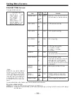
Reviews: