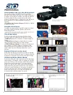
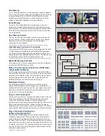

3D Compatibility: Switch up to Nine 3D Image Inputs
Mounting the optional AV-HS04M7D 3D SDI Output Board
provides 3D compatibility. Eight pairs of 3D images standard, and
a maximum of nine pairs of 3D images, can be input by dual SDI
from 3D cameras and other sources, with two-channel bus
switching. Transitions include cut, dissolve and wipe. Ideal for 3D
sports acquisition, TV commercial production, and event
recording.
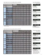
• Compatible video formats in 3D mode:
1080/59.94i, 1080/50i,
720/59.94p, 720/50p
Primatte® Chroma Keying
Primatte® chroma keying also supports 3D images (one channel
each, left and right). This enables real-time, high-precision
chroma keying on-site.
* Primatte® is a registered trademark of IMAGICA DIGIX Inc. Primatte® copyrights belong to
IMAGICA DIGIX Inc. Primatte® patents belong to IMAGICA DIGIX Inc.
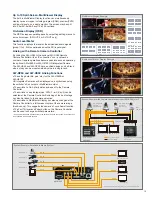
Three LR Mix Outputs
The LR mix image output function allows the left and right
channels of stereo 3D images to be checked on a 2D monitor.
• LRMIXa (LR mix a):
The L channel and R channel images are
mixed.
• LRMIXb (LR mix b):
Magenta is mixed within the L channel
image and green is mixed within the R channel image.
• LRDiff (LR difference display):
The luminance components of
the L channel and R channel images are compared, and the
difference between them is displayed using a gray scale. This
makes it easier to see the differences between the L and R
channels.
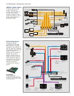
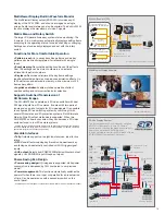
Rig-Type 3D Camera Correction Assist
Vertical/horizontal reversing and position correction are possible
for all 16 channels of SDI standard inputs. This helps to adjust the
optical axis of a rig-type 3D camera when producing 3D footage.
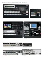
3D Video Signal Status Monitor Displays
This function overlays 3D video signal status monitor (brightness,
RGB distribution, LR difference, grid) on 3D image onto the PGM
output and PVW output (1/4 size only) of the MultiViewer Display.
Being able to check the differences in the leaping effect and
depth of the PGM and PVW without having to wear 3D glasses
makes 3D switching easier and smoother. Even when 3D assist
information cannot be displayed on the monitor or viewfinder of a
rig-type or other 3D camera, this function will feed back PVW
output to the camera so you can correct the brightness and
horizontal/vertical positioning right on the camera.
“Simulated” images were produced in
order to describe the function.
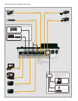
AG-3DP1G Integrated Twin-Lens
3D Camera Recorder
R
L
R
L
R
L
R
LRMIXa
LRMIXb
LRDiff
L ch Image
R ch Image
Histogram of amount of parallax (L ch and R ch)
Amount of parallax
Approx.
-7.5 %
Approx.
-3 %
0 %
Approx.
+3 %
Approx.
+7.5 %
Signal component level
(luminance, R, G and B)
Higher
Lower
Higher
Lo
w
er
Bar used for input signal (L ch and R ch) compensation
Grid
Lum, Red, Green, Blue
Prllx
●
Distribution of Lch and Rch signal components
●
Distribution of amount of parallax in 3D images
●
A grid is displayed at intervals of about 3 % along
the width of the screen.
Dist
rib
ution
amounts of l
ev
els
Higher
Lo
w
er
Dist
rib
ution of
amount of pa
rallax
Green display area:
Indicates a distribution with many L ch components.
Red display area:
Indicates a distribution with many R ch components.
Select LRMIXa or LRMIXb as the 3D output format,
and shoot so that the amount of parallax between Lch
and Rch come within the grid width.
Recessed
direction
Jutting out
direction
Mirror
Vertical Reversal/Positioning
Mirror
Horizontal Reversal/Positioning
5


